The 970-HA-JOKES Payphone Project
 Nate
Nate 
Original Payphone
The original payphone housing is from 1987 if the stamps are to be believed. The mechanical engineering behind a payphone is the culmination of 80 years of cat and mouse warfare. The phone companies wanted to make money, and tons of people tried to find ways not to pay it (slugs, Captain Crunch Whistles, etc).
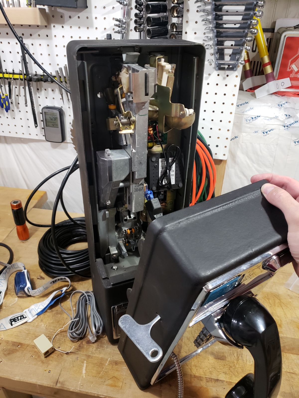
The entire housing is thick steel with an incredible locking mechanism for the top portion and a separate and even denser area for the bottom area, called the ‘vault’ that collects the money. Just the phone (no pedestal or shroud) weighs 45 pounds.
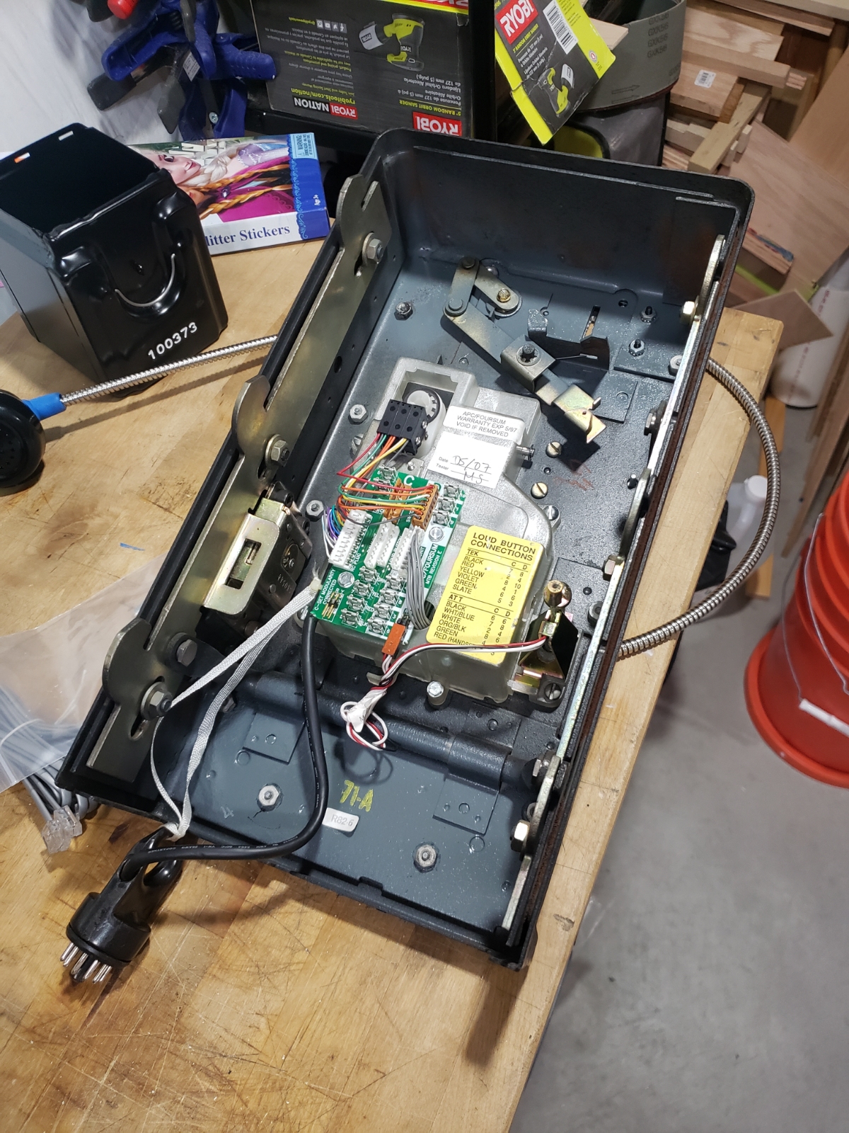
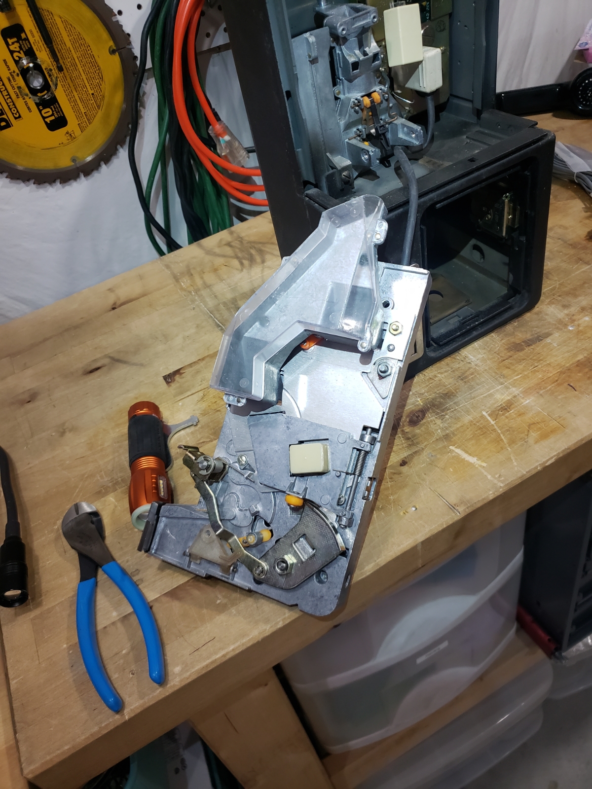
Here is the back side of the front face containing the hook, keypad, and handset wiring. What’s better than a hook switch? Four hook switches. I’m sure there is some very sneaky design going on. At least I can understand the four wires coming in from the handset:
- Mic+
- Mic-
- Speaker+
- Speaker-
The entire front face connects to the mainboard within the phone base through the large chunky black ring connector. Even that has some innovation: the white ribbon is a tether that is shorter than the black data cable connecting the connector to the front face. When a technician is lifting off the not light weight front face, if they pull directly out, the tether tightens and pulls the plug from the mainboard, all without having to take two hands from holding the face. Very handy.
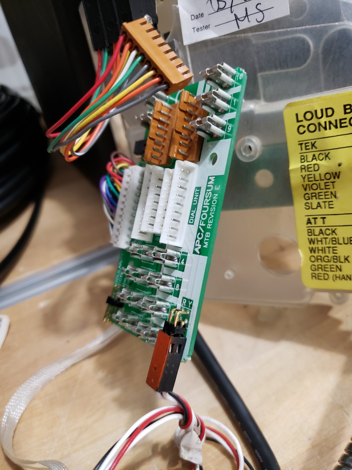
This is a closeup of the hook board from the front face. It looks like an aftermarket part that allows a myriad of different hook and keypad types. My guess is that it’s a universal interface board of sorts.
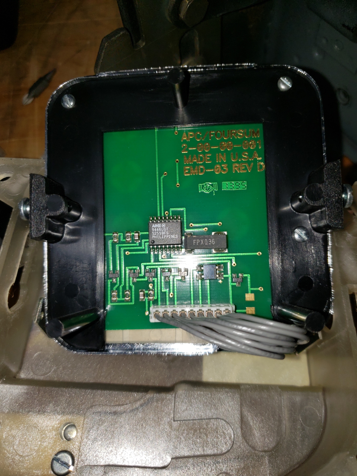
Buried underneath the hook interface board is the keypad. I assumed the keys were, like any matrix keypad, connected to the phone’s main board where it would handle the deciphering of which key was pressed. I was planning on this because I needed the Arduino to know what button was being pressed. But I was surprised to find the keypad had its own DTMF encoder built into it! The keypad generates the tones itself that are then passed back to the mainboard over the microphone connection. Sneaky.
On the left is the AMI 9446LGT S2559FS DTMF encoder IC. On the right is the crystal that drives the IC. Here is the datasheet for the AMI S2559E/F IC.
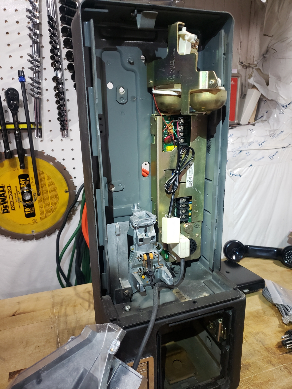
Here is the main board within the main phone housing with ringer up top. The company I bought the phone from had installed the RJ11 cable and coupler to make it easier for at-home use.
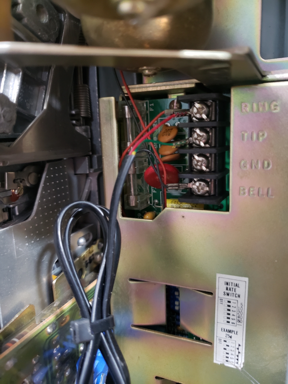
Here is a close up of that wiring. This configuration basically circumvents the mainboard and wires the phone straight through so no coins are required to place a call.
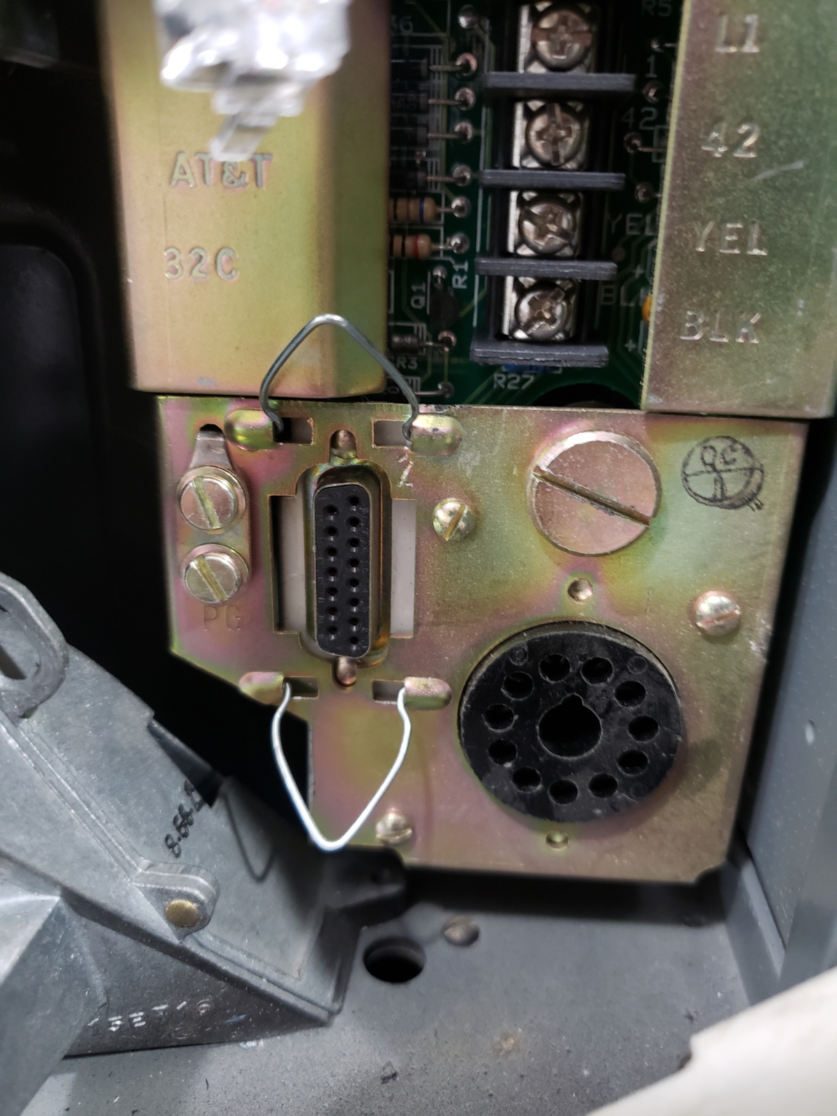
Up top are the four connection points to the phone companies’ phone line.
On the left is the 15 pin connector that connects to the coin acceptor.
On the right is the 11 pin circular connector to the front face.
Nothing interesting about the ringer, other than the fact that its metallic clang still gives me the pure anticipation I felt growing up: Who could it be? Can I make it to the one phone in our house before my siblings?
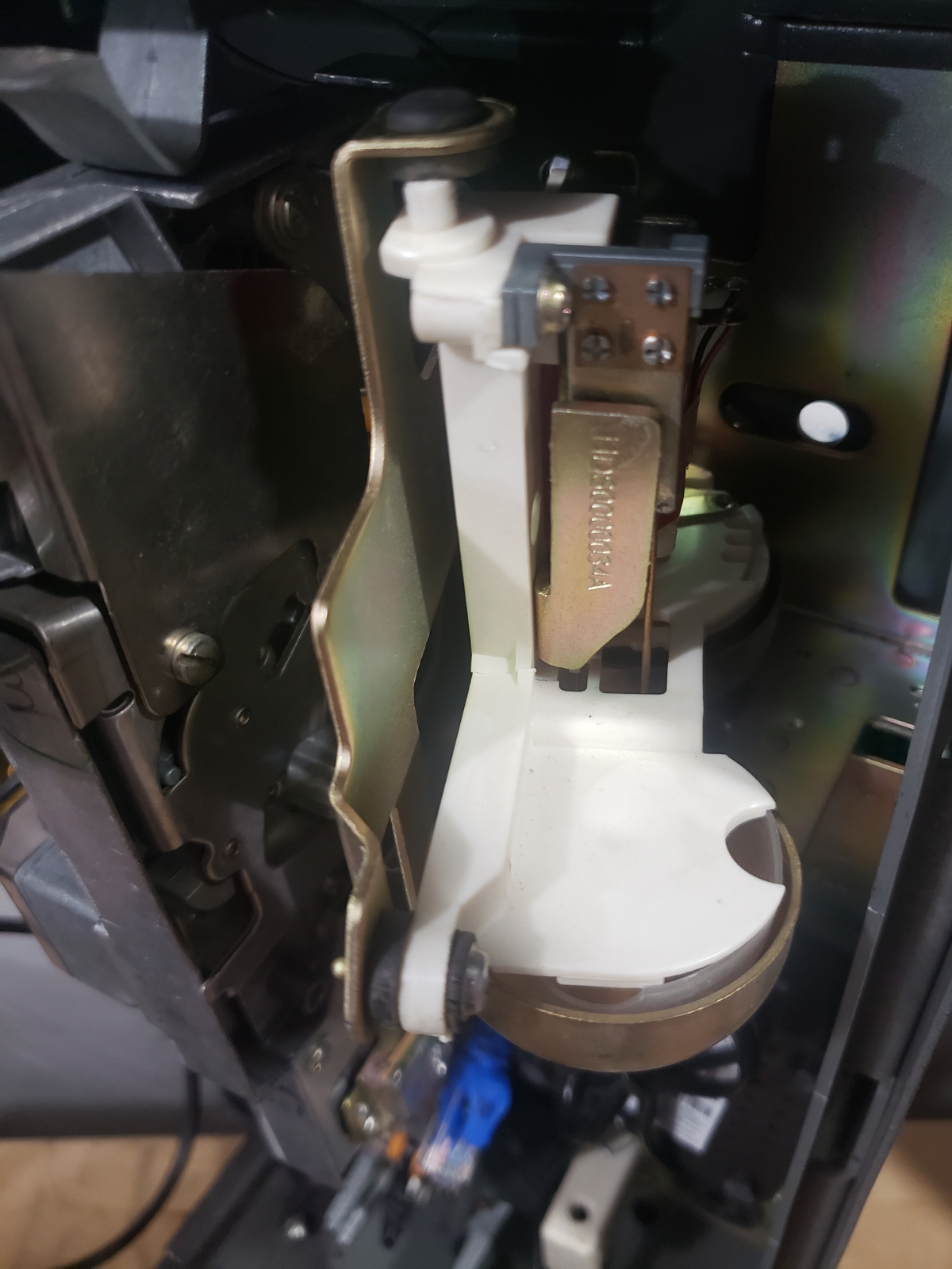
Here is the coin validator/detector. More on that later.
The aluminum shroud and pedestal were also delivered:
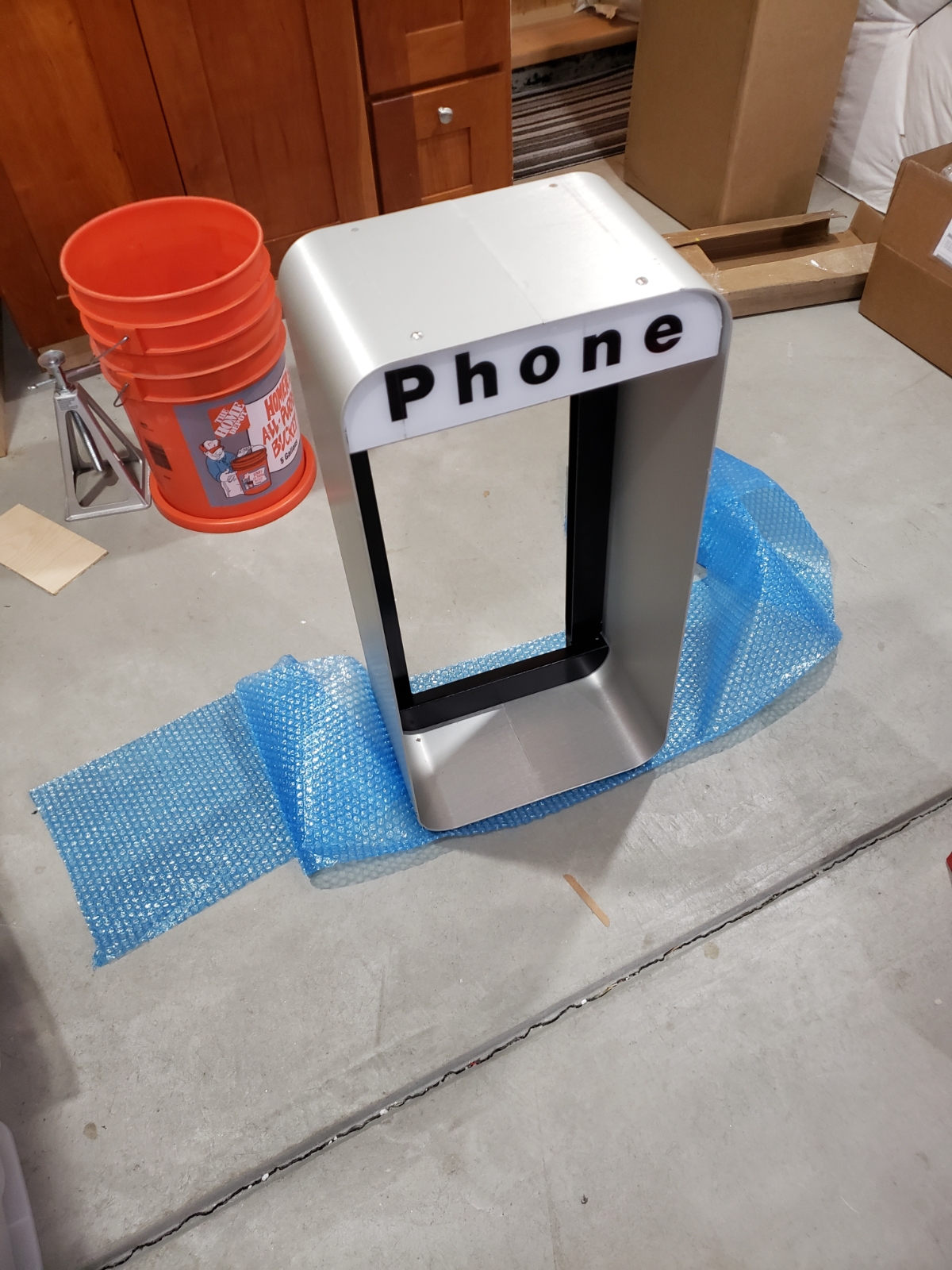
Unwrapping this was like Christmas.
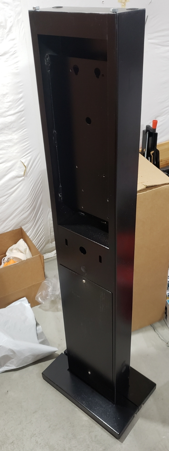
The pedestal weighed another 45 pounds. It came very well packaged and protected, complete with a bag of bolts and sweet, sweet, security screws.
The great thing about the phone shroud and pedestal was that it was designed to allow for lots of large cables going in and out of the phone, usually originating from the ground. This gave me lots of ways to wire power and data.
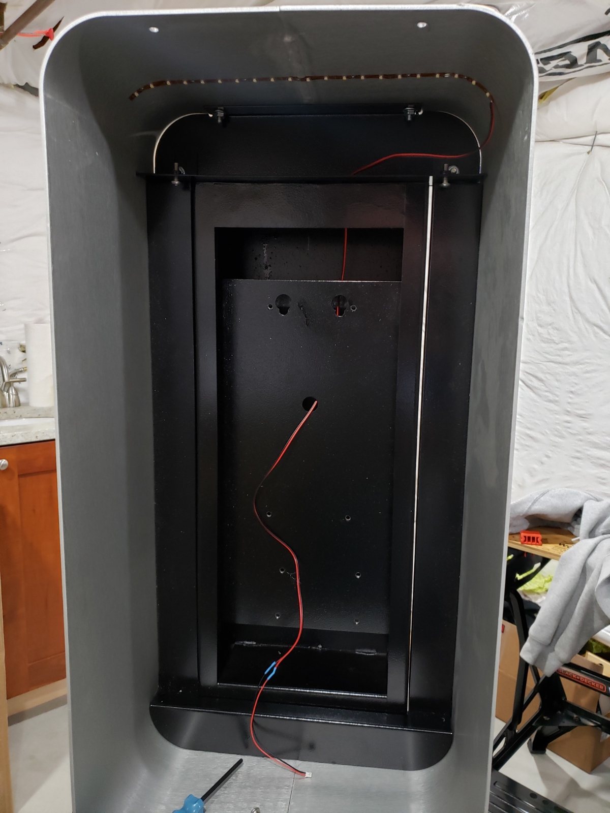
This was crucial because the phone sign up top needed a little something...
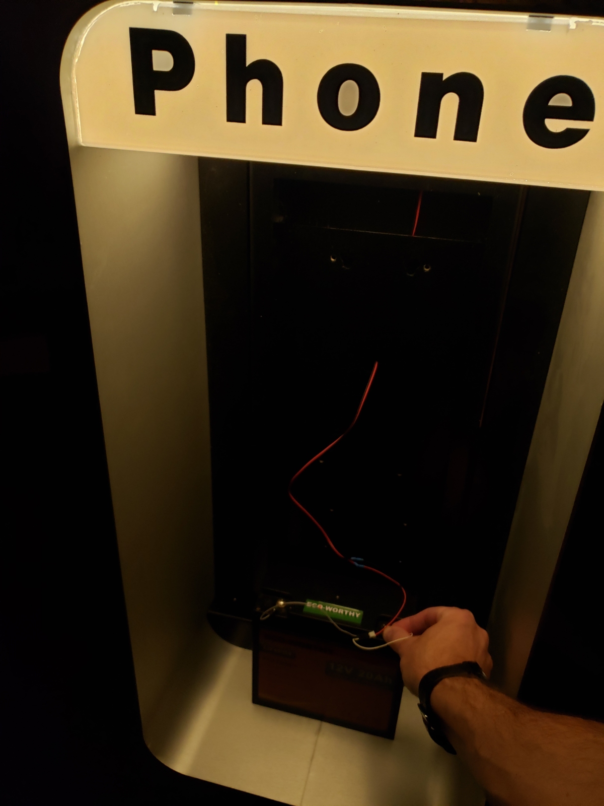
Ahhhh, that’s better. A short strip of 12V warm white LEDs make it glow nicely. You can also see one of the LiFePO4 batteries that was used to power the overall phone.
With the phone parts mostly pulled apart and inspected it was time to figure out the electronics.