The 970-HA-JOKES Payphone Project
 Nate
Nate 
Introduction
Do you miss buttons? Coins? Questionable publicly shared surfaces?
Have a listen to this classic hold music on infinite loop and be taken back to a time when pay phones ruled the street corner and peppered the mall food court.
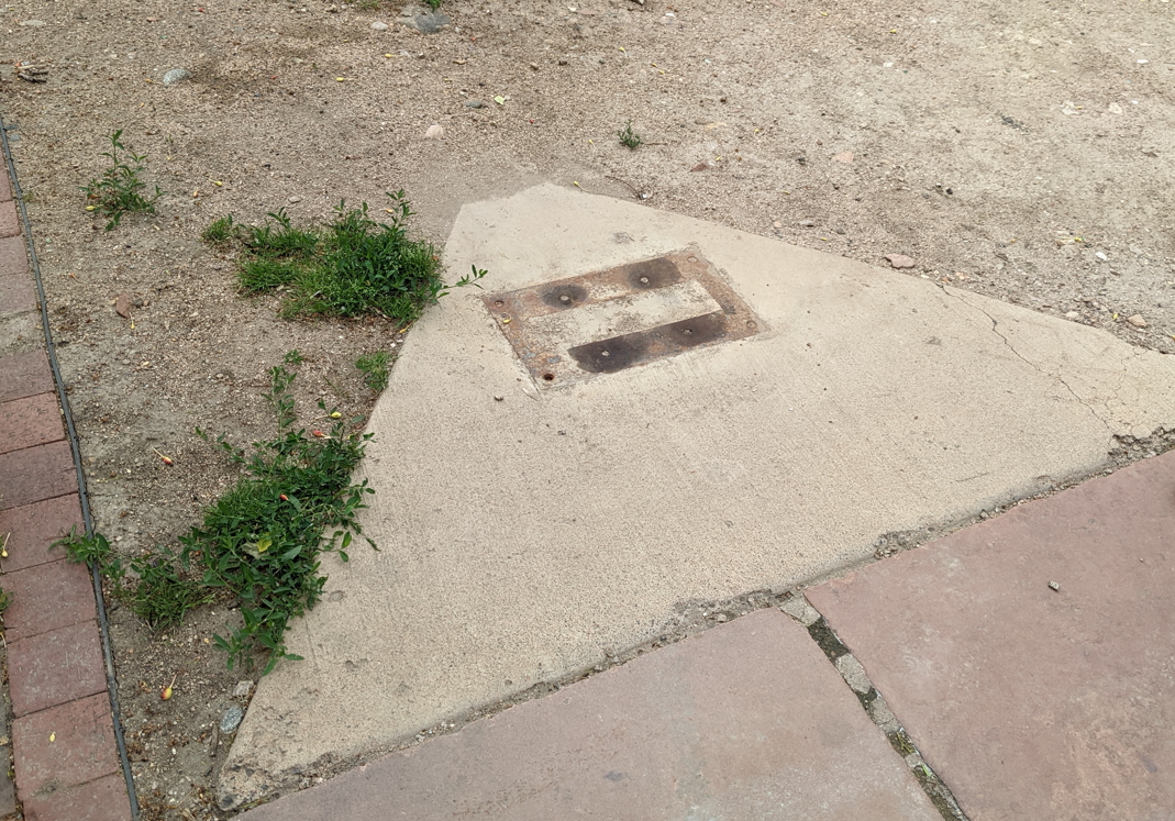
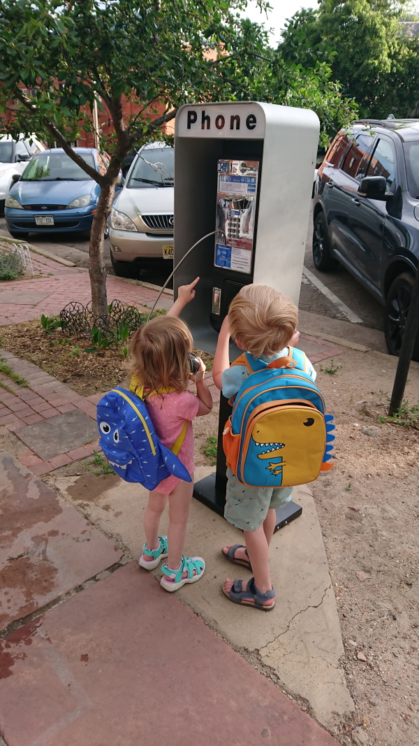
It all started because they moved the parking meters around my neighborhood. When our city (Boulder) got new pay stations, they left behind concrete pads with metal mount points.
I mentioned to my wife, ‘wouldn’t it be funny if someone put a payphone there?’. She agreed, and down the rabbit hole I went... This is not the first time she has led me to fun projects.
Ever since I was a kid I wanted to take apart a payphone. The first time I called my parents for a ride home from a payphone outside the movie theater I noticed the screws and the locks. I had basic knowledge of screws and these were obviously hex bolts, but what were the pegs in the middle? Fast forward 30 years and obviously everything has changed. You can buy security screw bits at the local hardware store, and payphones are a thing of the past, but the retro curiosity was still there. If I was going to covertly put a payphone out on the street, we better make some people giggle before we get in trouble.
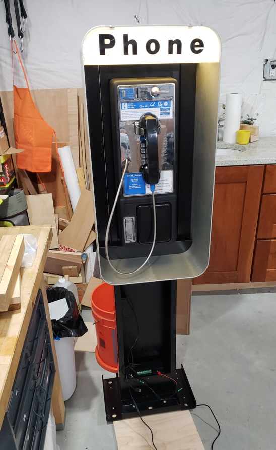
The 970-HA-JOKES Payphone Project is an Arduino based, fully functional, payphone that utilizes VOIP over WiFi, with a bunch of easter eggs built in. Let’s dig in.
Where Do You Get a Payphone?
While there are a variety of payphones on ebay at flea markets, it’s very tricky to find a legitimately procured payphone. Also, it’s next to impossible to find one with locks. To save time, but at expense, I ended up getting a PP100 with an L31 Enclosure and floor mount pedestal for a little over $1000 shipped from payphone.com. I didn’t need a truly functional payphone since I was going to mod the heck out of it, but being able to order keys and locks along with the phone, shroud, and pedestal saved me tremendous amounts of time and frustration.
Learning how the phone worked was another challenge. There are incredible forums and piles of resources available (Vintage Arcade Preservation Society, Classic Rotary Phones Forum, among many others), but as with most hobbies and bygone professions, the acronyms are impenetrable and ‘where do I start?’ tutorials are non-existent. In summary, the main controller board detects when a valid coin has passed the coin detector, and transmits tones back to the phone switch. Power is provided via the phone line itself (sometimes fed by local power as well). When the correct amount of money is detected, the call is connected to the phone network.
How does the Payphone Project work?
It's simple really (joke!). Here's how the Payphone Project worked: take a phone and make it VOIP enabled. And require that a coin be deposited before allowing the call. Oh and be really sure 911 is available and can be dialed without a coin. Also, the phone is kind of far away so the VOIP will have to be WiFi based. And there's no power available so it will have to run on batteries. And wouldn't it be funny if the phone played a silly MP3 if someone called 867-5309?
It got a bit complex but hey, what did you do during COVID?
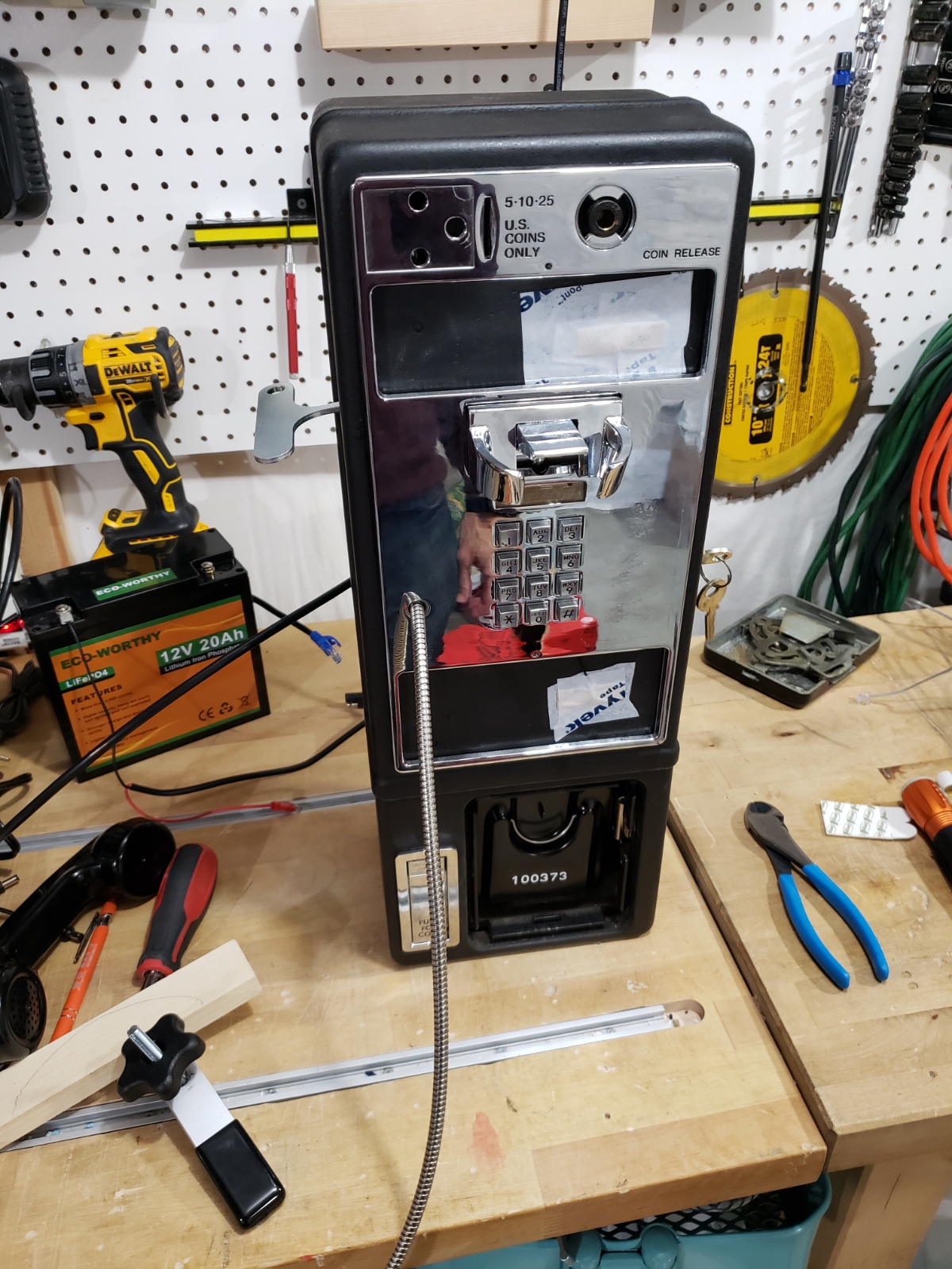
Original Payphone
The original payphone housing is from 1987 if the stamps are to be believed. The mechanical engineering behind a payphone is the culmination of 80 years of cat and mouse warfare. The phone companies wanted to make money, and tons of people tried to find ways not to pay it (slugs, Captain Crunch Whistles, etc).
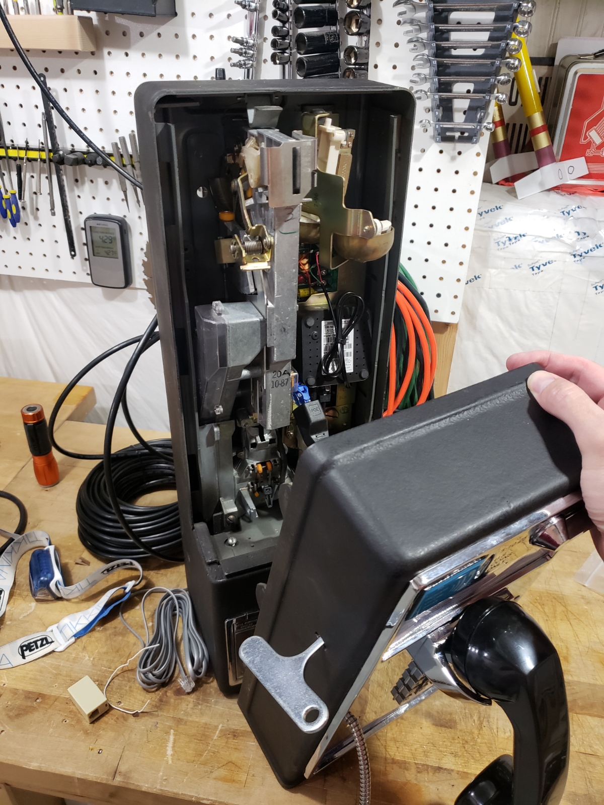
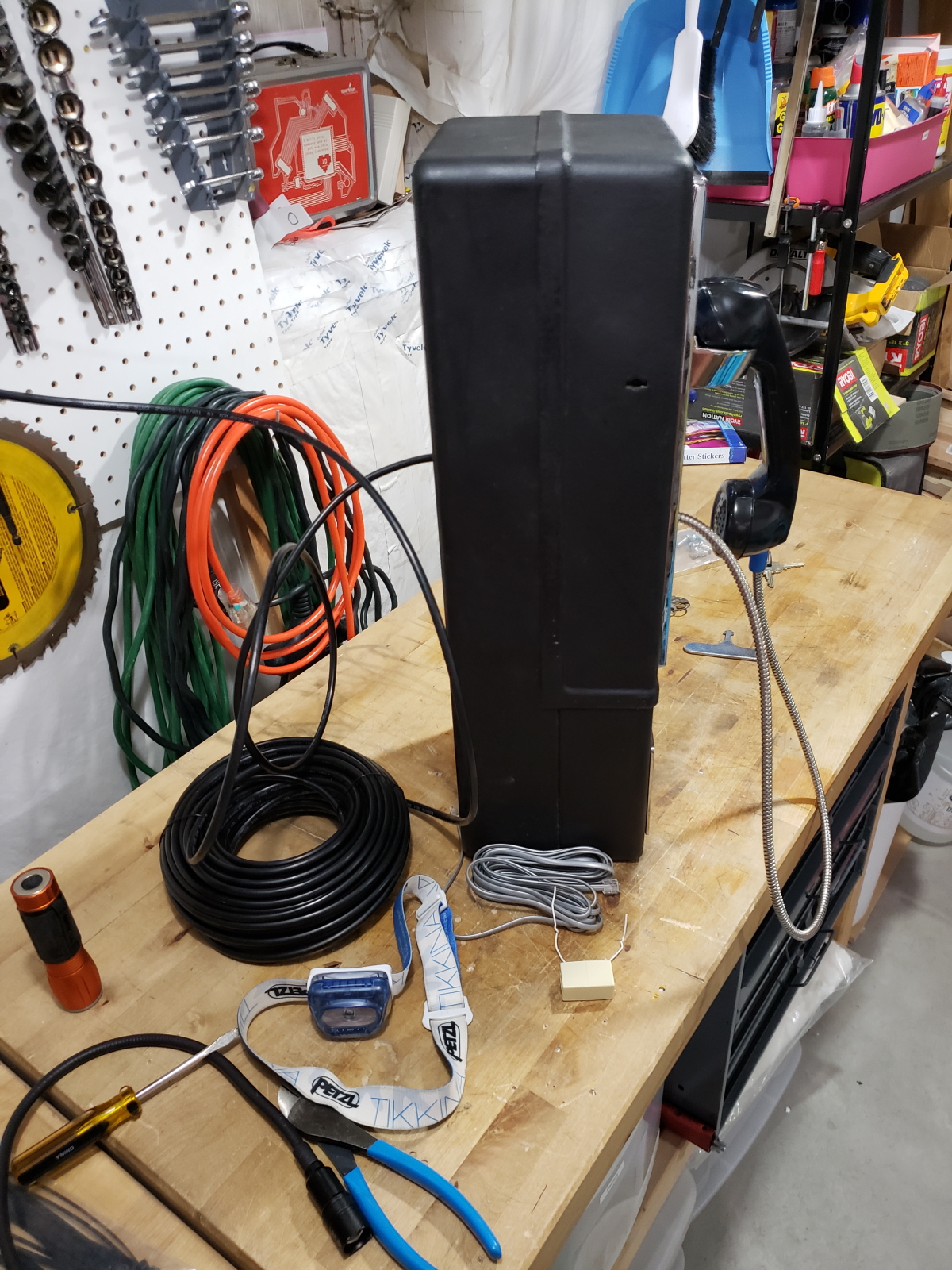
The entire housing is thick steel with an incredible locking mechanism for the top portion and a separate and even denser area for the bottom area, called the ‘vault’ that collects the money. Just the phone (no pedestal or shroud) weighs 45 pounds.
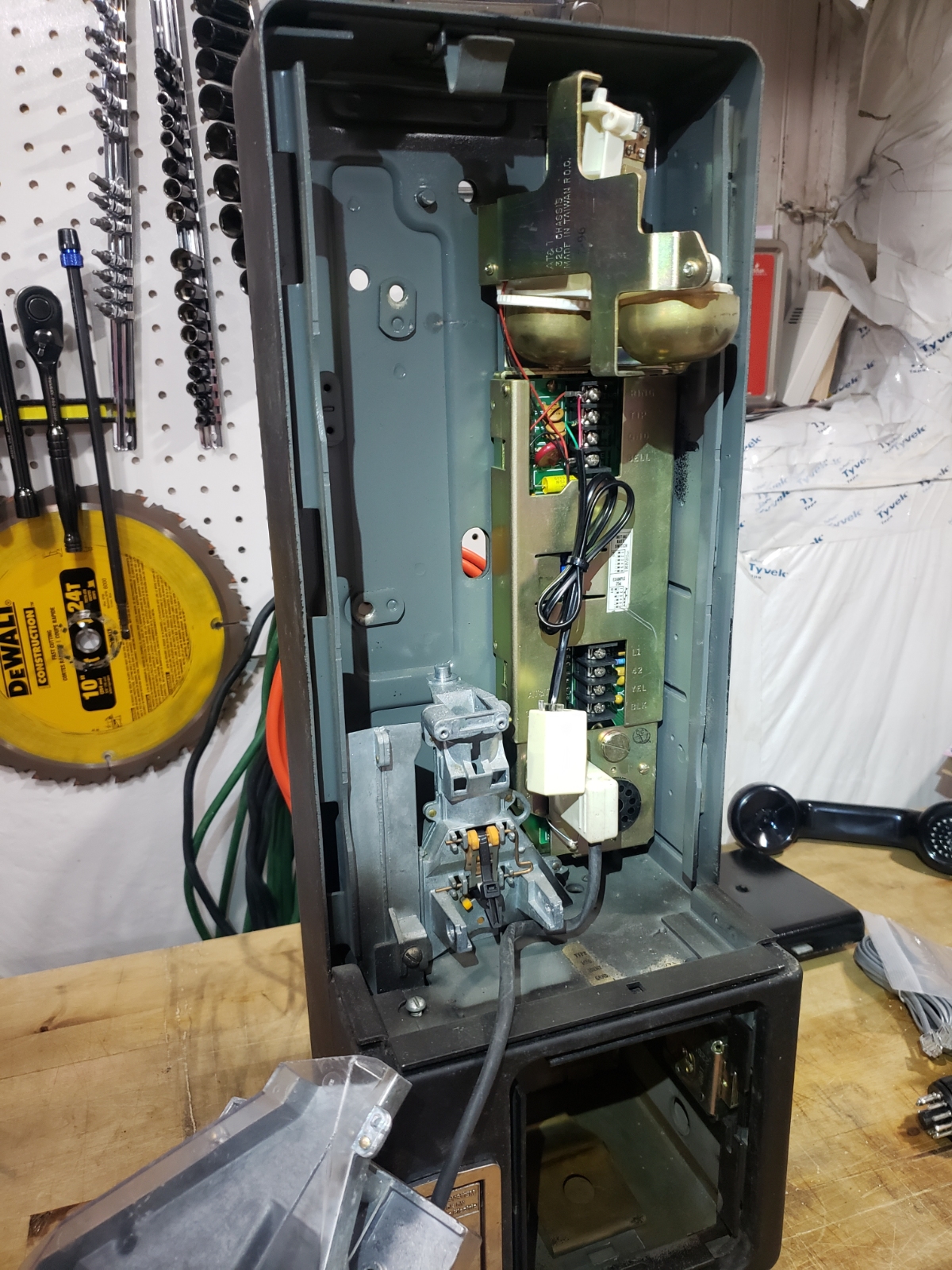
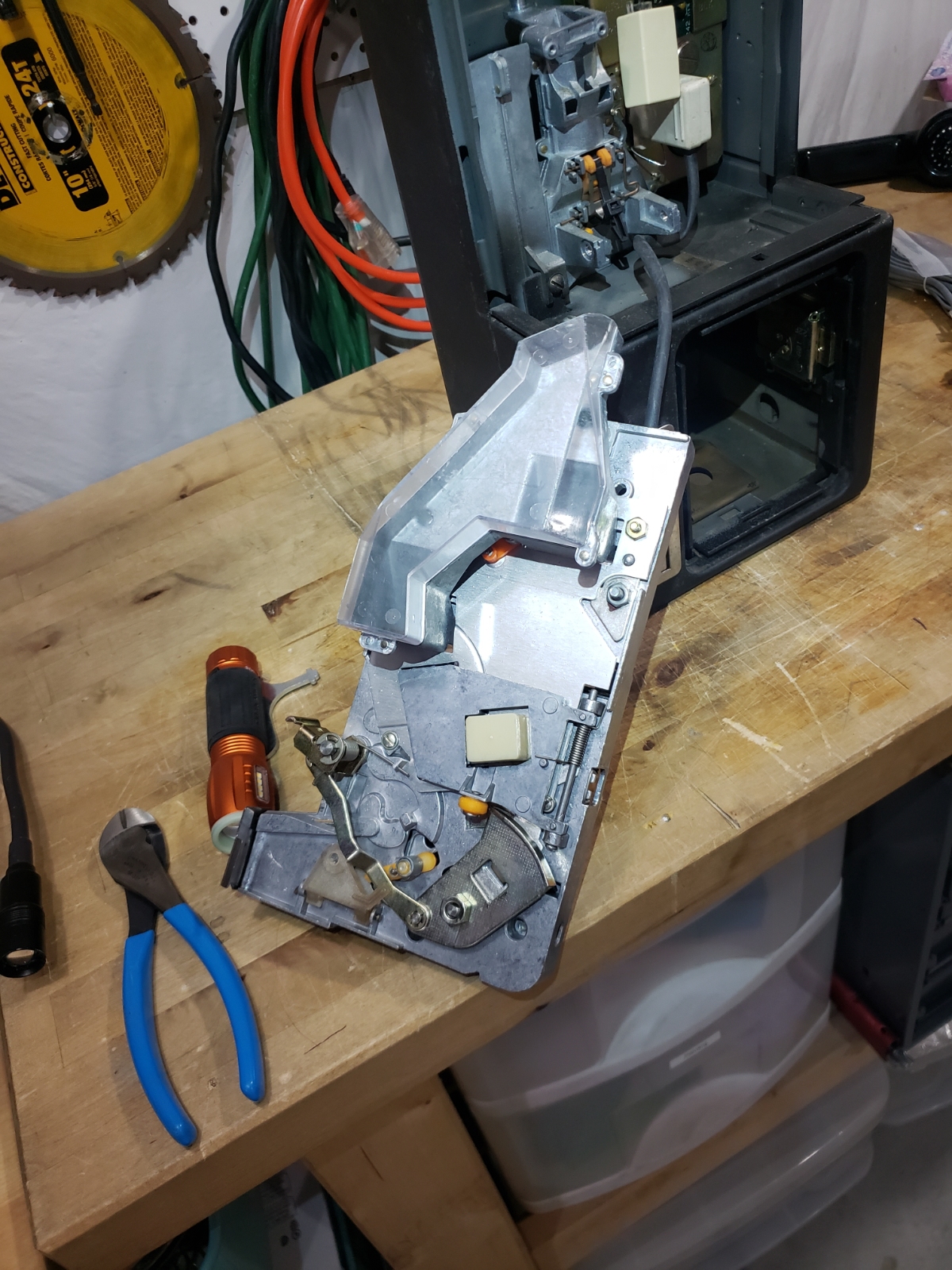
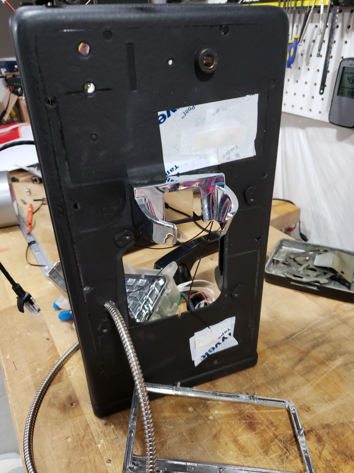
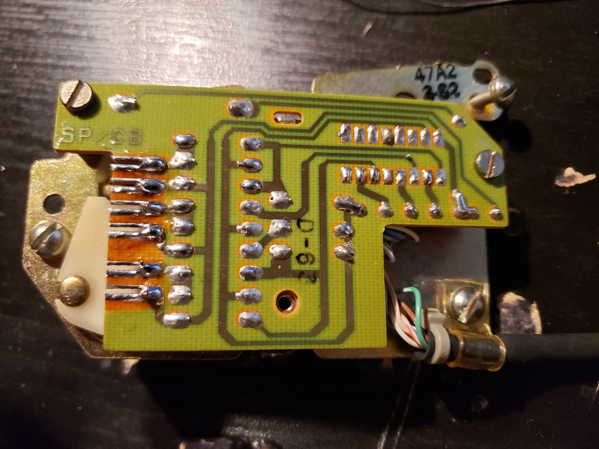
Here is the back side of the front face containing the hook, keypad, and handset wiring. What’s better than a hook switch? Four hook switches. I’m sure there is some very sneaky design going on. At least I can understand the four wires coming in from the handset:
- Mic+
- Mic-
- Speaker+
- Speaker-
The entire front face connects to the mainboard within the phone base through the large chunky black ring connector. Even that has some innovation: the white ribbon is a tether that is shorter than the black data cable connecting the connector to the front face. When a technician is lifting off the not light weight front face, if they pull directly out, the tether tightens and pulls the plug from the mainboard, all without having to take two hands from holding the face. Very handy.
This is a closeup of the hook board from the front face. It looks like an aftermarket part that allows a myriad of different hook and keypad types. My guess is that it’s a universal interface board of sorts.
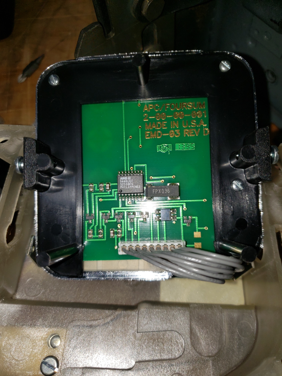
Buried underneath the hook interface board is the keypad. I assumed the keys were, like any matrix keypad, connected to the phone’s main board where it would handle the deciphering of which key was pressed. I was planning on this because I needed the Arduino to know what button was being pressed. But I was surprised to find the keypad had its own DTMF encoder built into it! The keypad generates the tones itself that are then passed back to the mainboard over the microphone connection. Sneaky.
On the left is the AMI 9446LGT S2559FS DTMF encoder IC. On the right is the crystal that drives the IC. Here is the datasheet for the AMI S2559E/F IC.
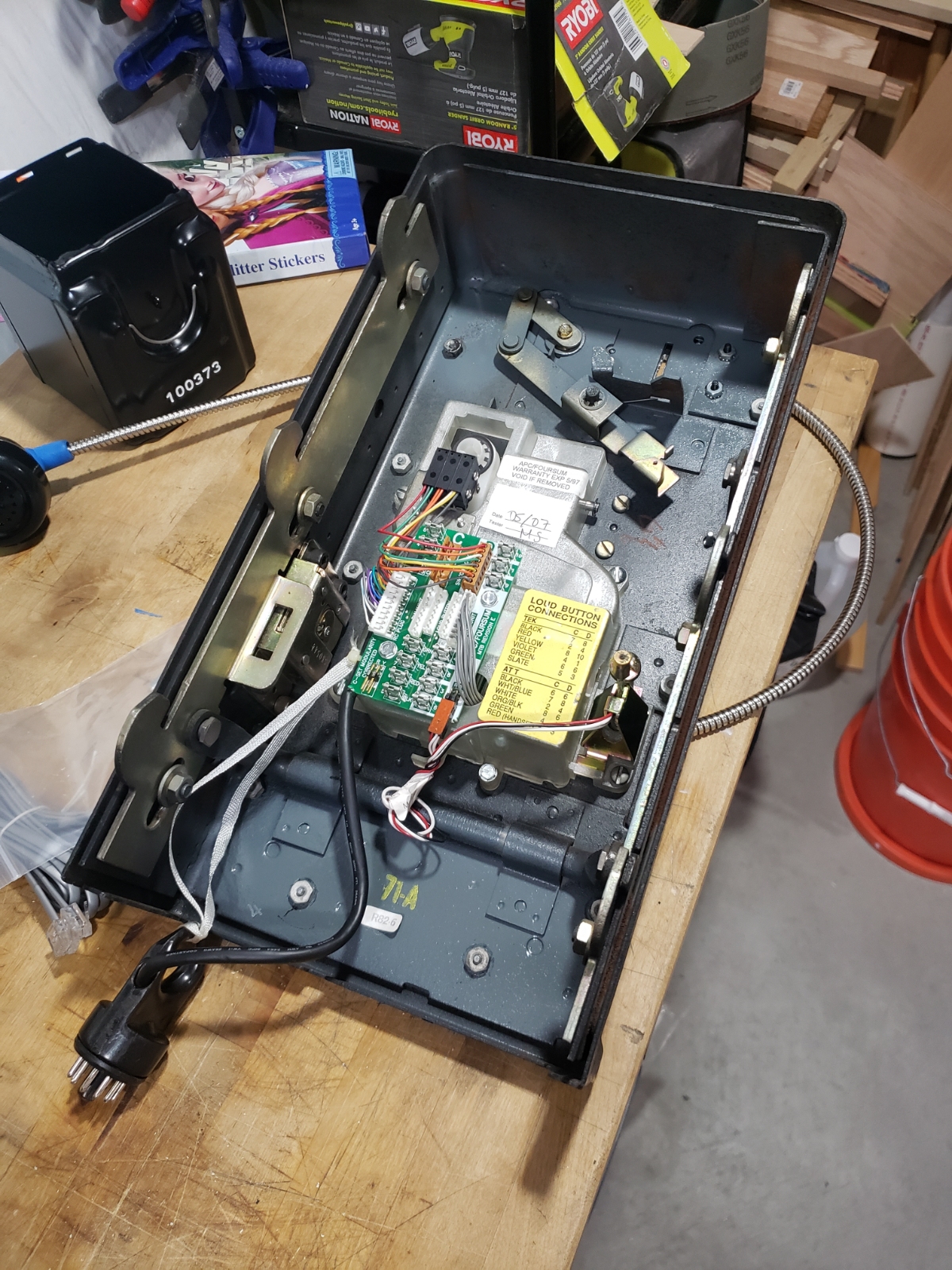
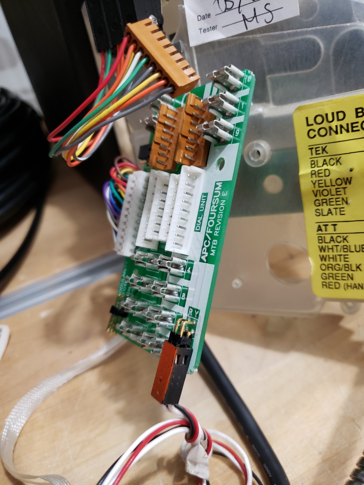
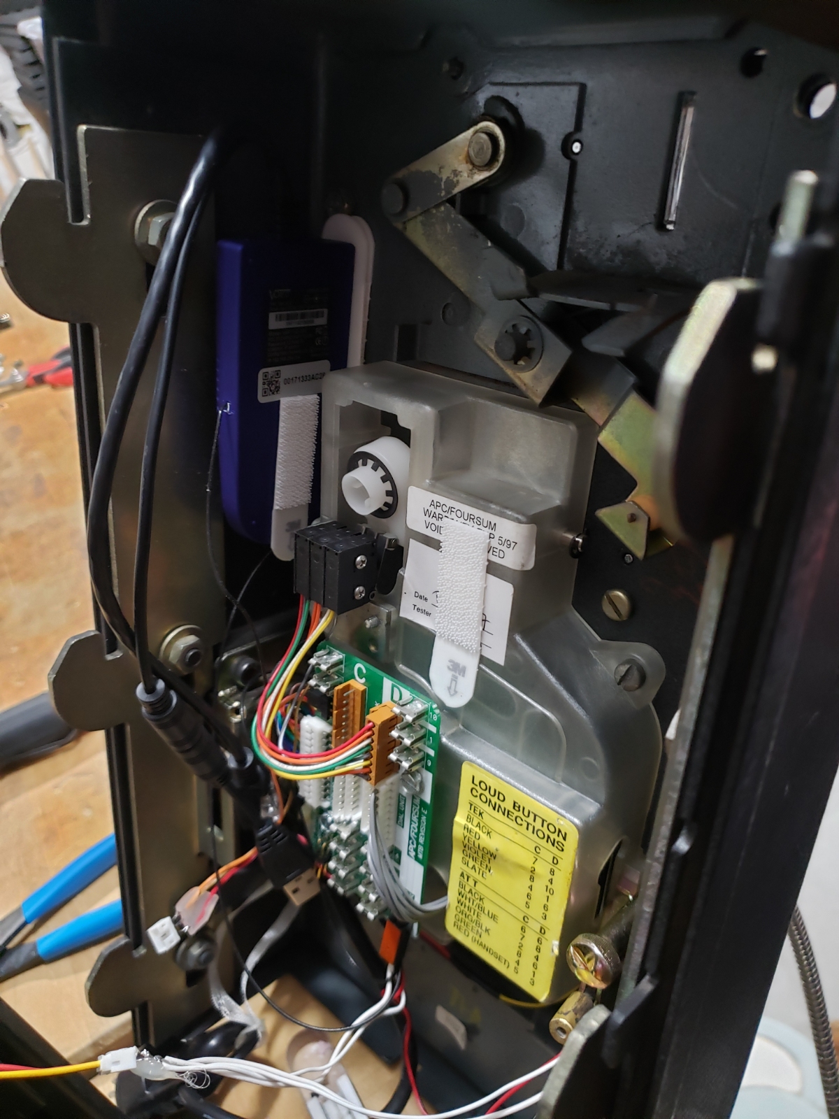
Here is the main board within the main phone housing with ringer up top. The company I bought the phone from had installed the RJ11 cable and coupler to make it easier for at-home use.
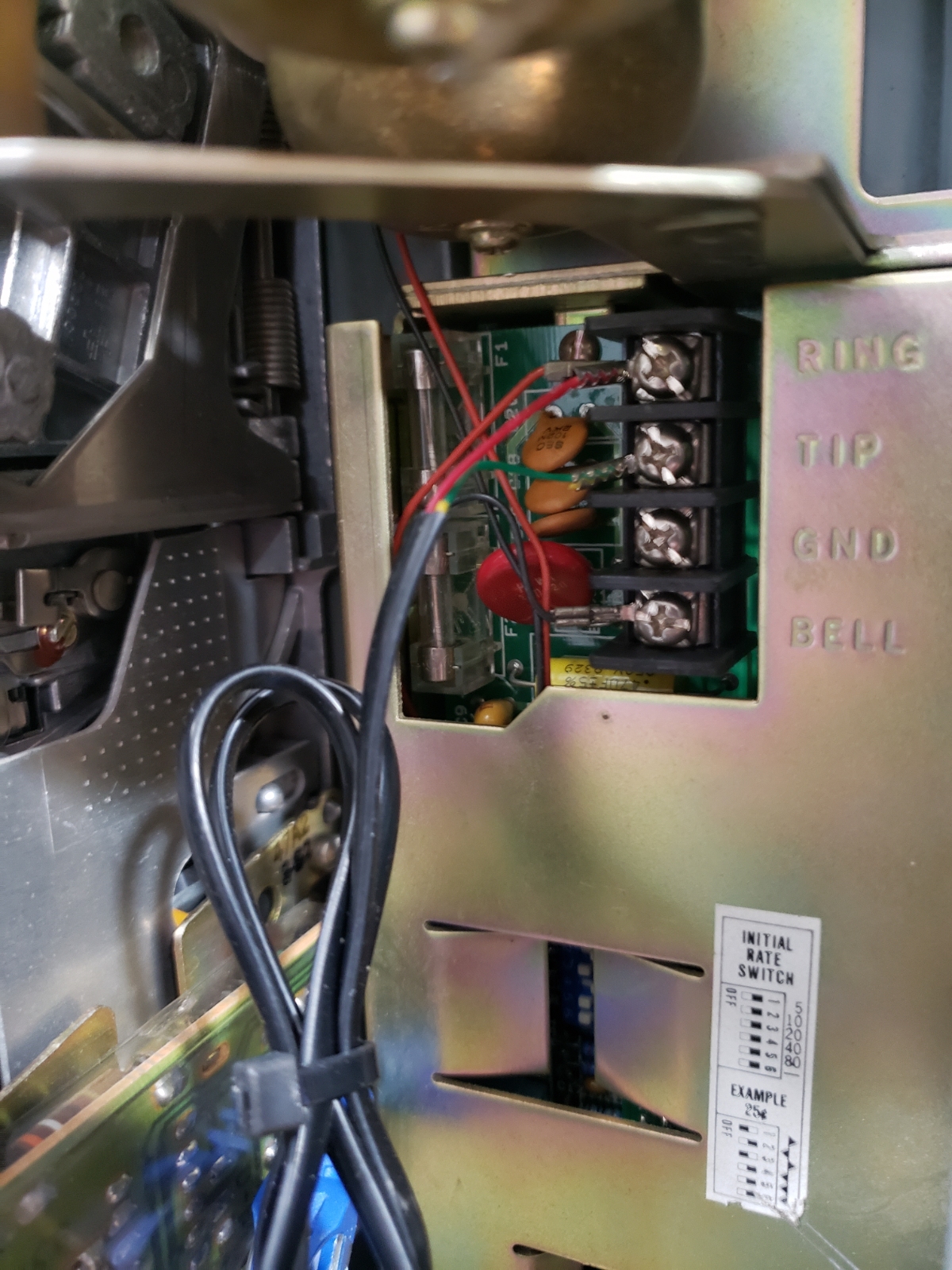
Here is a close up of that wiring. This configuration basically circumvents the mainboard and wires the phone straight through so no coins are required to place a call.
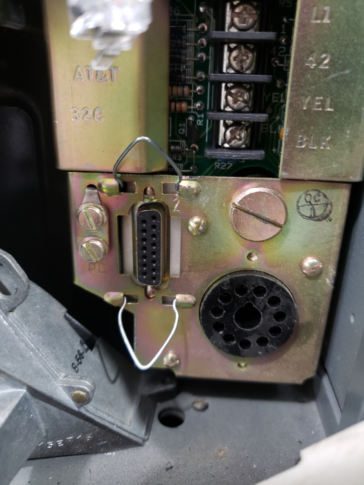
Up top are the four connection points to the phone companies’ phone line.
On the left is the 15 pin connector that connects to the coin acceptor.
On the right is the 11 pin circular connector to the front face.
Nothing interesting about the ringer, other than the fact that its metallic clang still gives me the pure anticipation I felt growing up: Who could it be? Can I make it to the one phone in our house before my siblings?
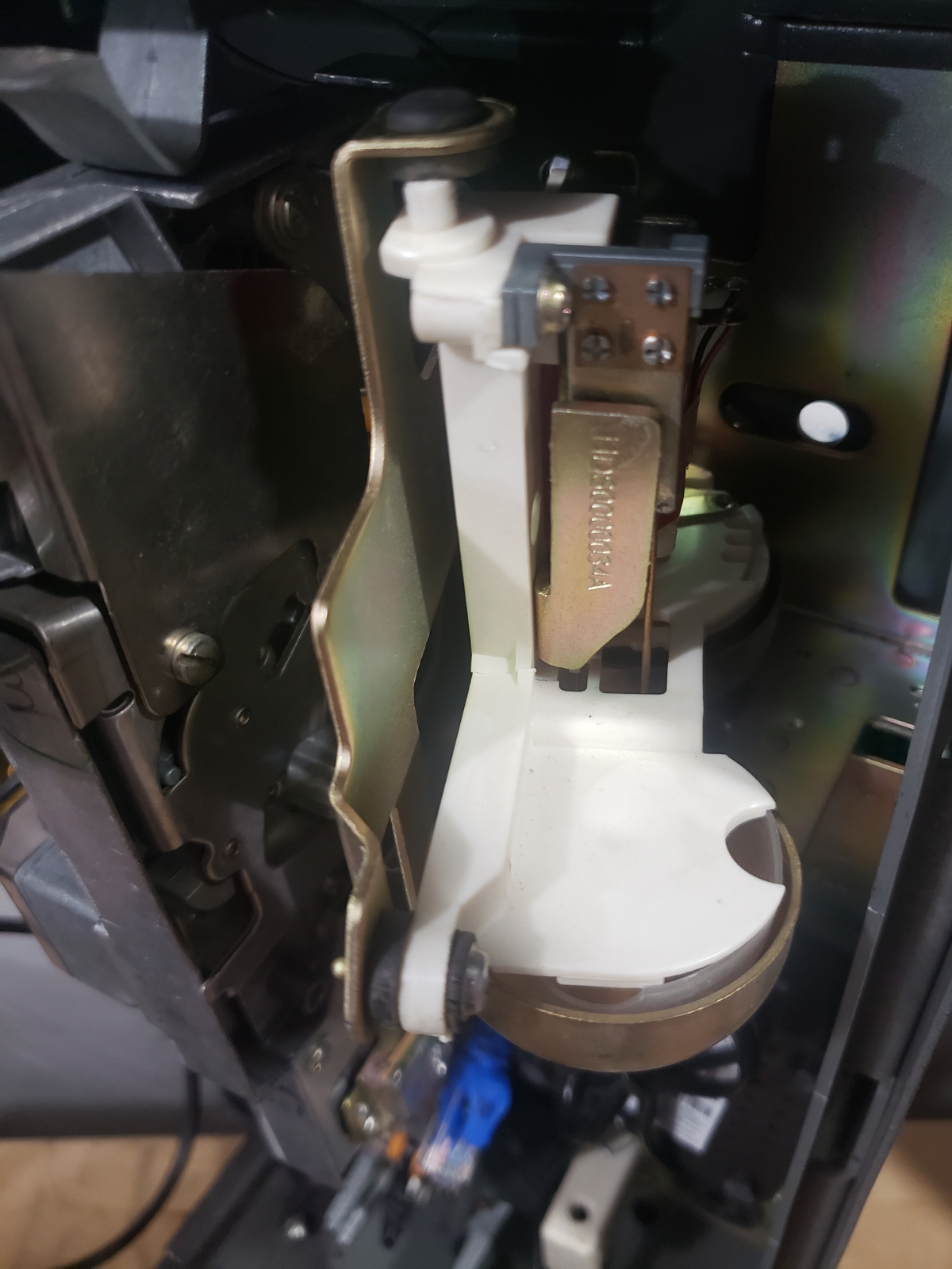
Here is the coin validator/detector. More on that later.
The aluminum shroud and pedestal were also delivered:
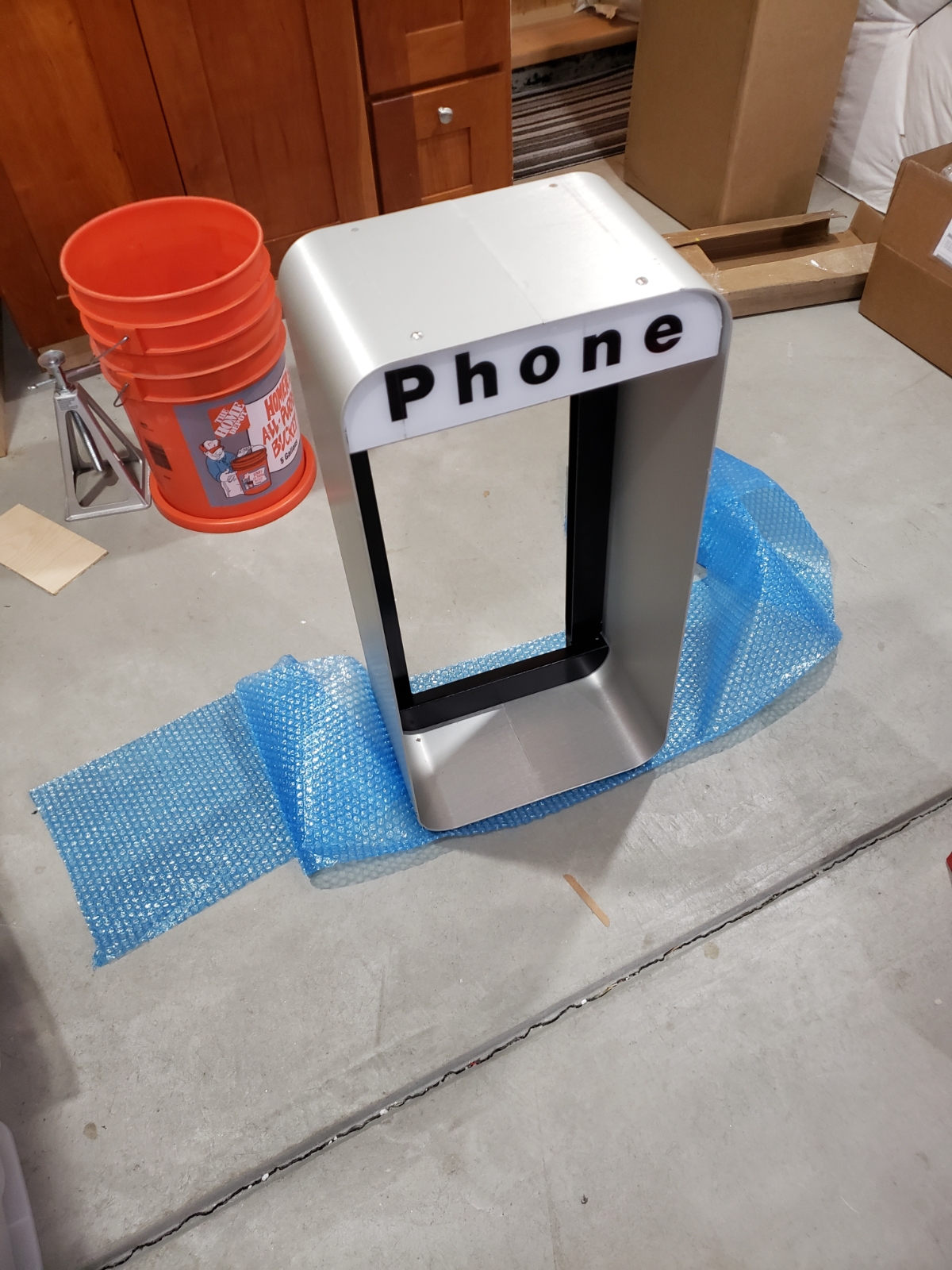
Unwrapping this was like Christmas.
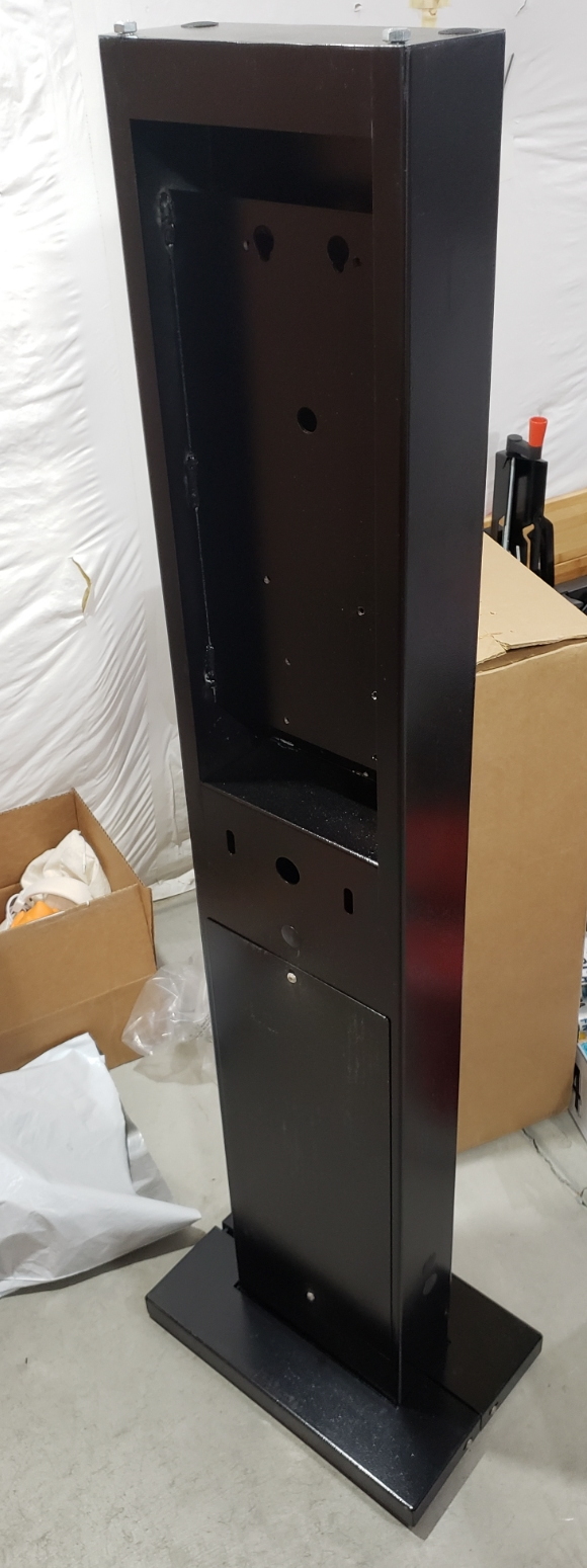
The pedestal weighed another 45 pounds. It came very well packaged and protected, complete with a bag of bolts and sweet, sweet, security screws.
The great thing about the phone shroud and pedestal was that it was designed to allow for lots of large cables going in and out of the phone, usually originating from the ground. This gave me lots of ways to wire power and data.
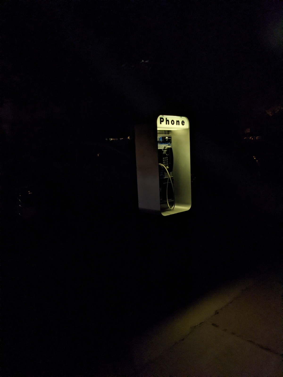
This was crucial because the phone sign up top needed a little something...
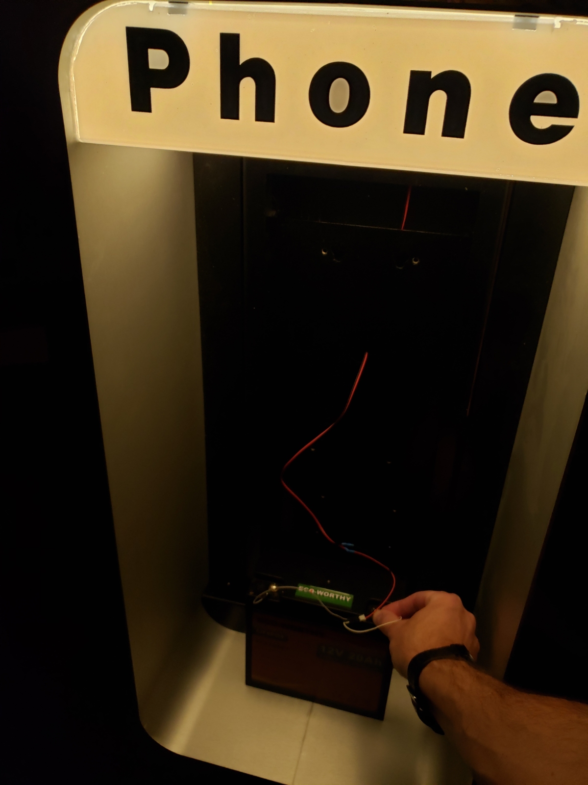
Ahhhh, that’s better. A short strip of 12V warm white LEDs make it glow nicely. You can also see one of the LiFePO4 batteries that was used to power the overall phone.
With the phone parts mostly pulled apart and inspected it was time to figure out the electronics.
VOIP
At this point, VOIP technology is completely omnipresent. It’s cheap and easy to get an analog phone onto an ethernet network.
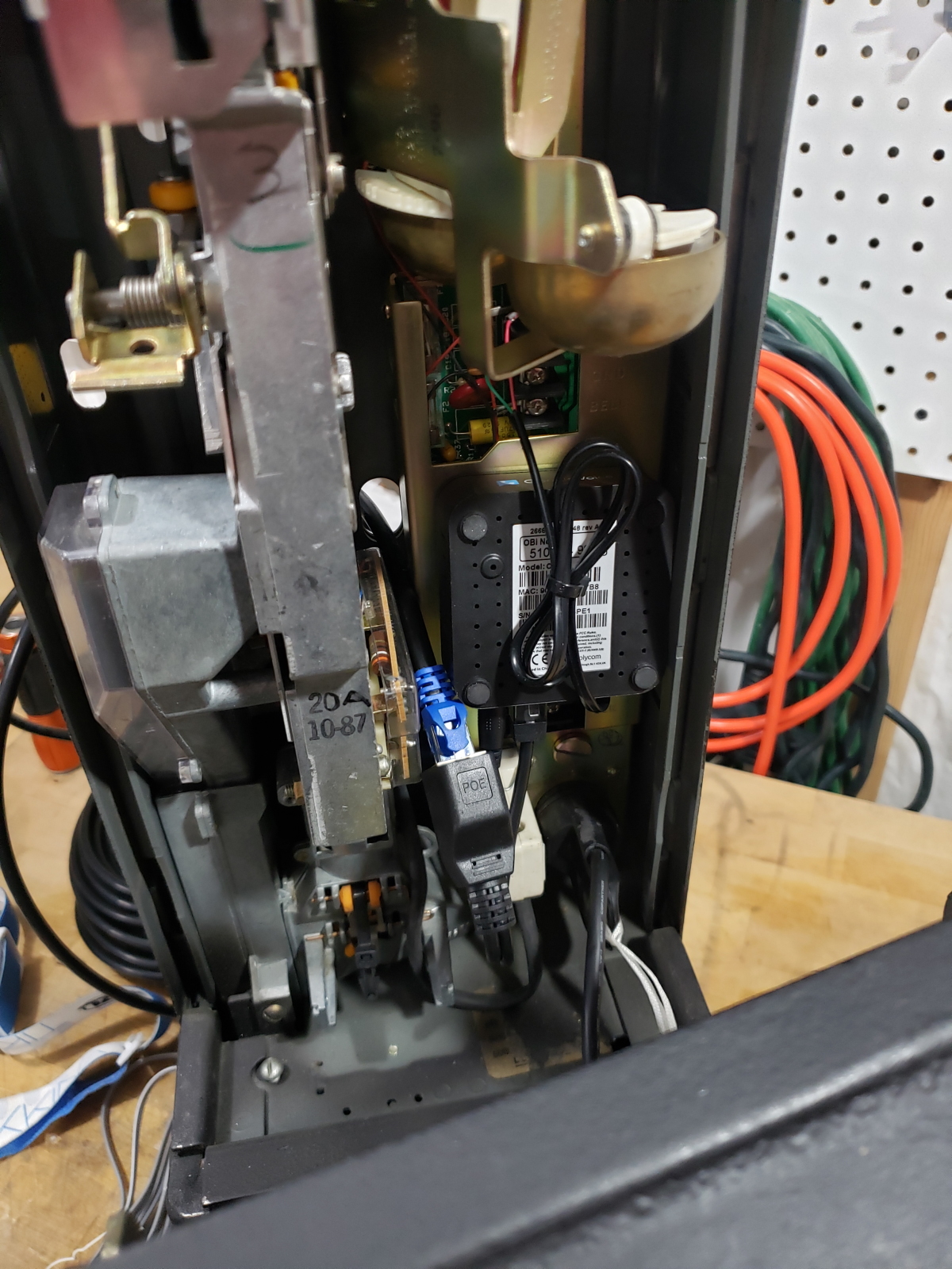
And while the inside of the phone housing was a little tight, getting an ObiHai Obi200 in there was not too hard. The Obi200 will move up and to the right of the ringer later on.
Calling my wife to ask her ‘Guess what I’m calling from?!?!?’ never happened because she didn’t recognize the Google Voice phone number and ignored it. I had to text her from my cell phone just to… You know what, never mind. I called her from a pay phone and it was AWESOME.
WiFi
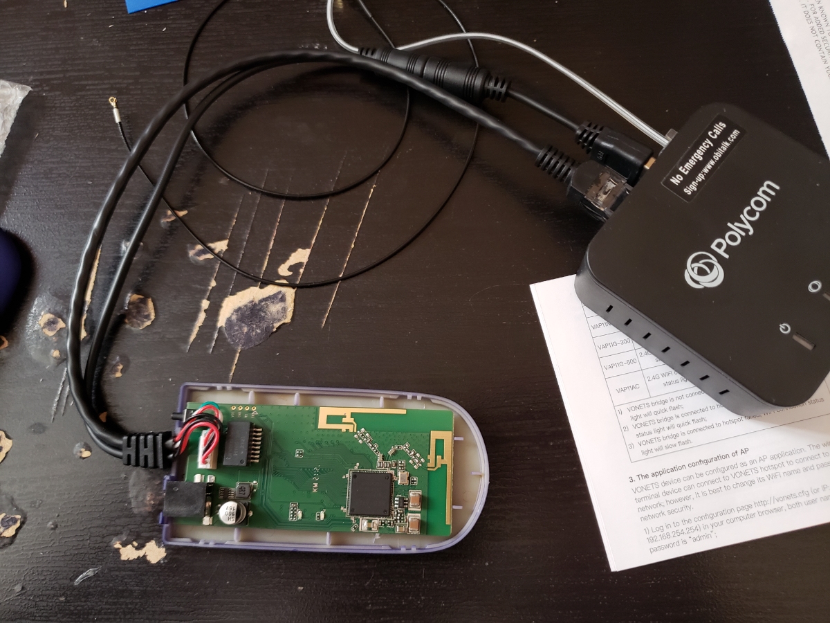
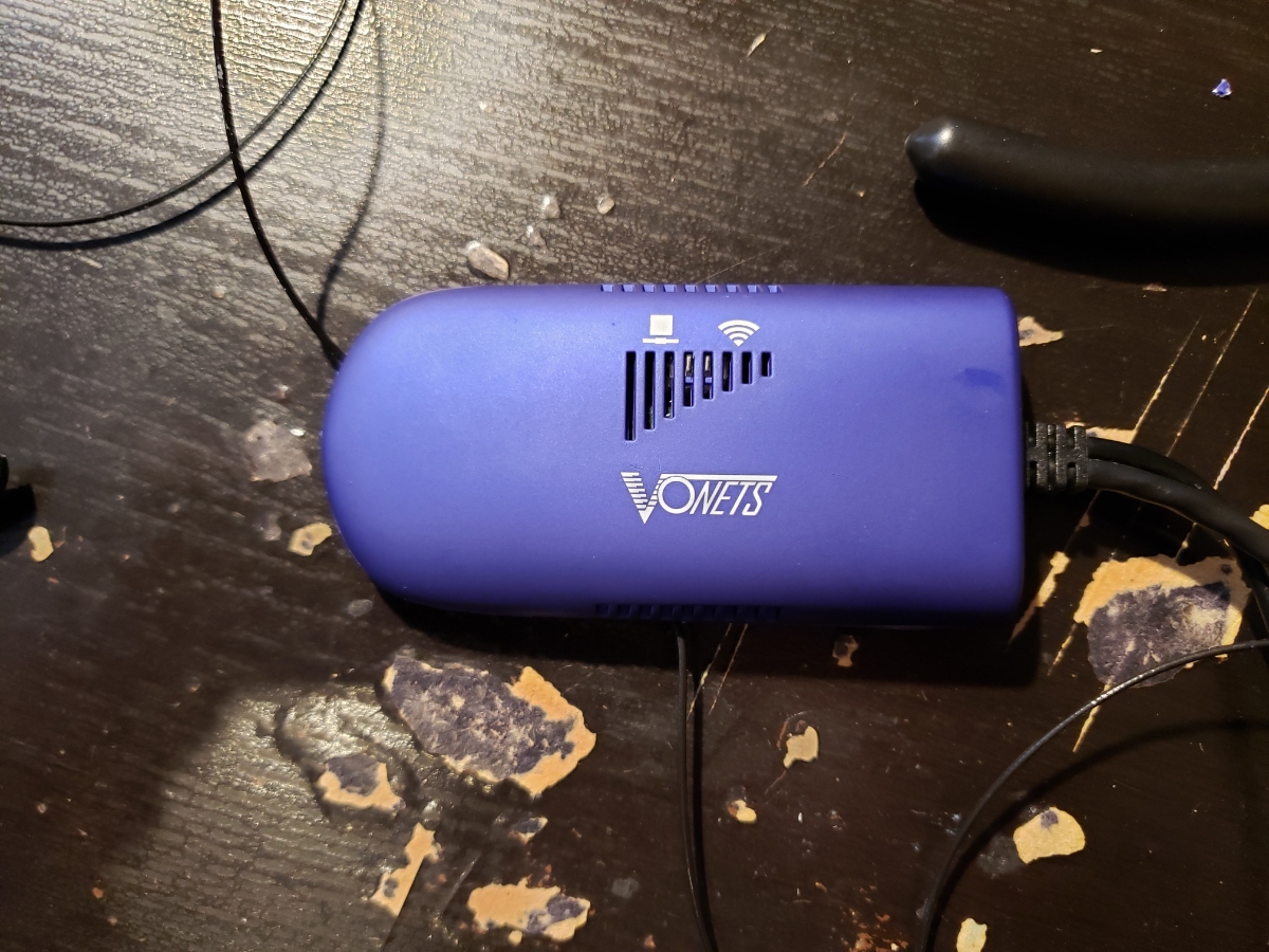
VOIP works but the phone would be located too far to run an ethernet cable. We convinced our friend who lives near the parking pad to allow us to use their WiFi ‘for a few days’. Thankfully, there are some off-the-shelf devices that are a simple WiFi to ethernet bridge. The VONETS VAP11G-300 fit the bill. Just plug it in and it’ll work, right? Unfortunately the metal tank of an enclosure reduced the PCB’s antenna reception terribly. If the phone was within ~10 feet of the WiFi access point, we could get reception but we need much further. Let’s change the antennas!
Of course I could have hung a couple rubber antennas off the back of the payphone enclosure, but that would completely ruin the experience. If you saw a payphone with antennas sticking out of the back, you’d know there was something going on. Where can we hide a pair of antennas so they still get reception? Hmm...
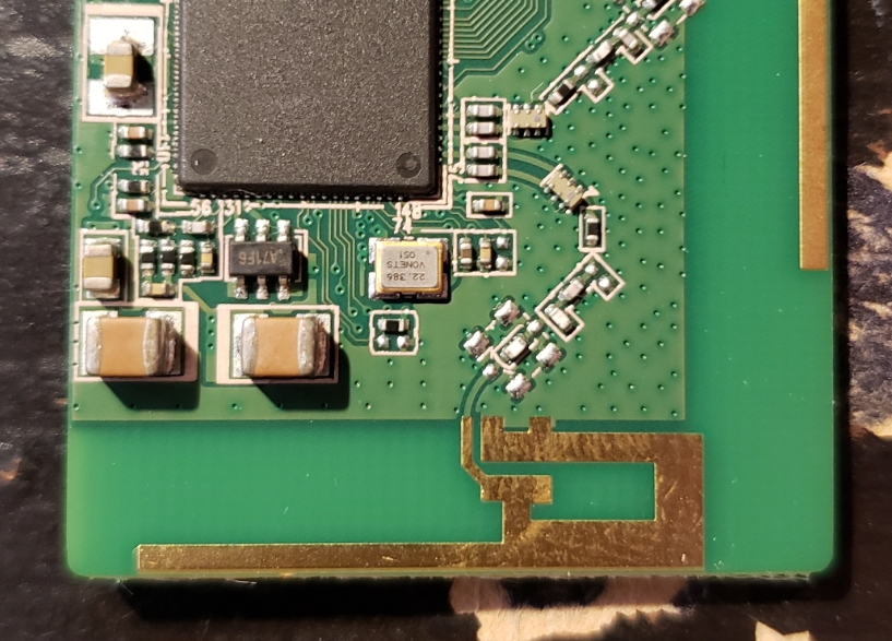
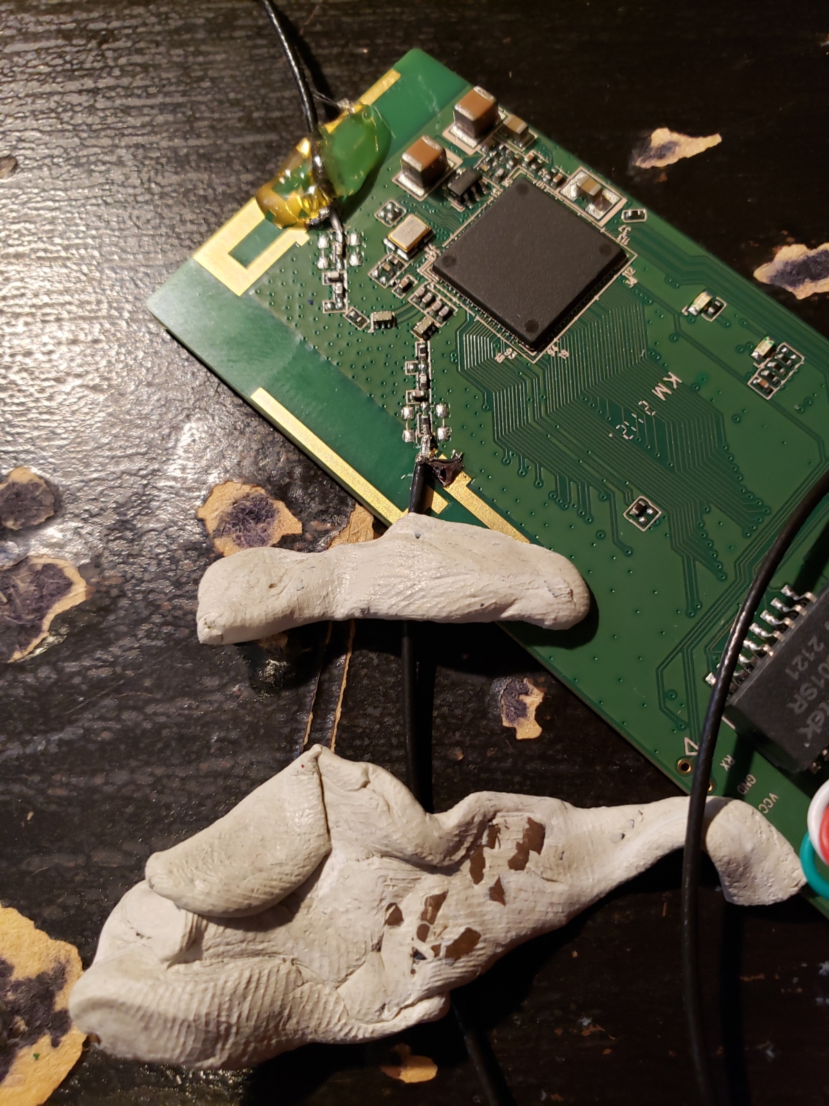
Above is the RF path connecting the IC to the PCB antenna.
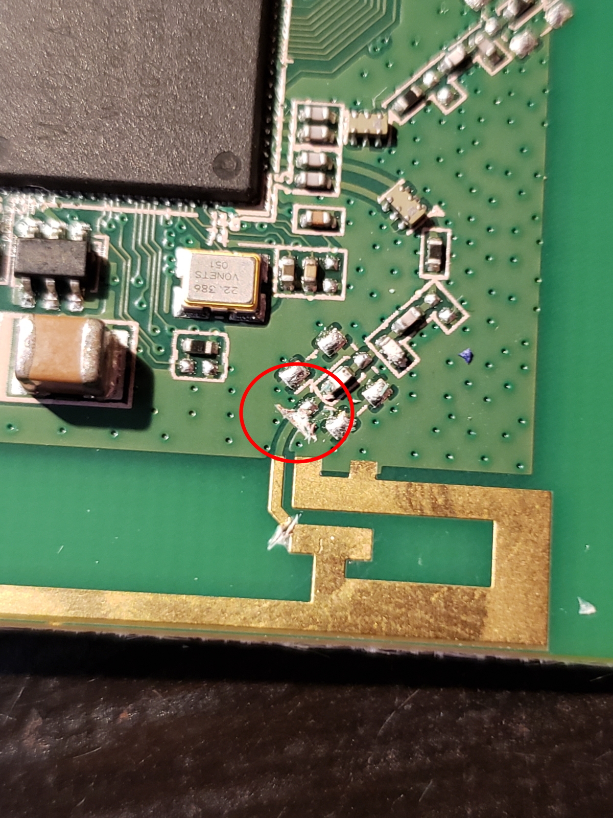
I made a cut to isolate the matching network from the PCB antenna. (The 2nd lower cut was unnecessary)
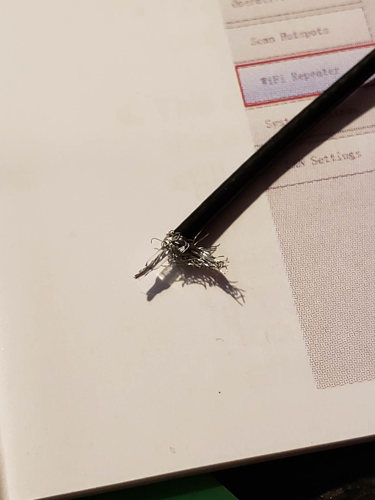
I cut the U.FL connector from a pair of 2.4GHz thin antennas and carefully stripped and exposed the signal pin and ground sheath.
Sticky tack is my favorite tool and makes an excellent 3rd hand.
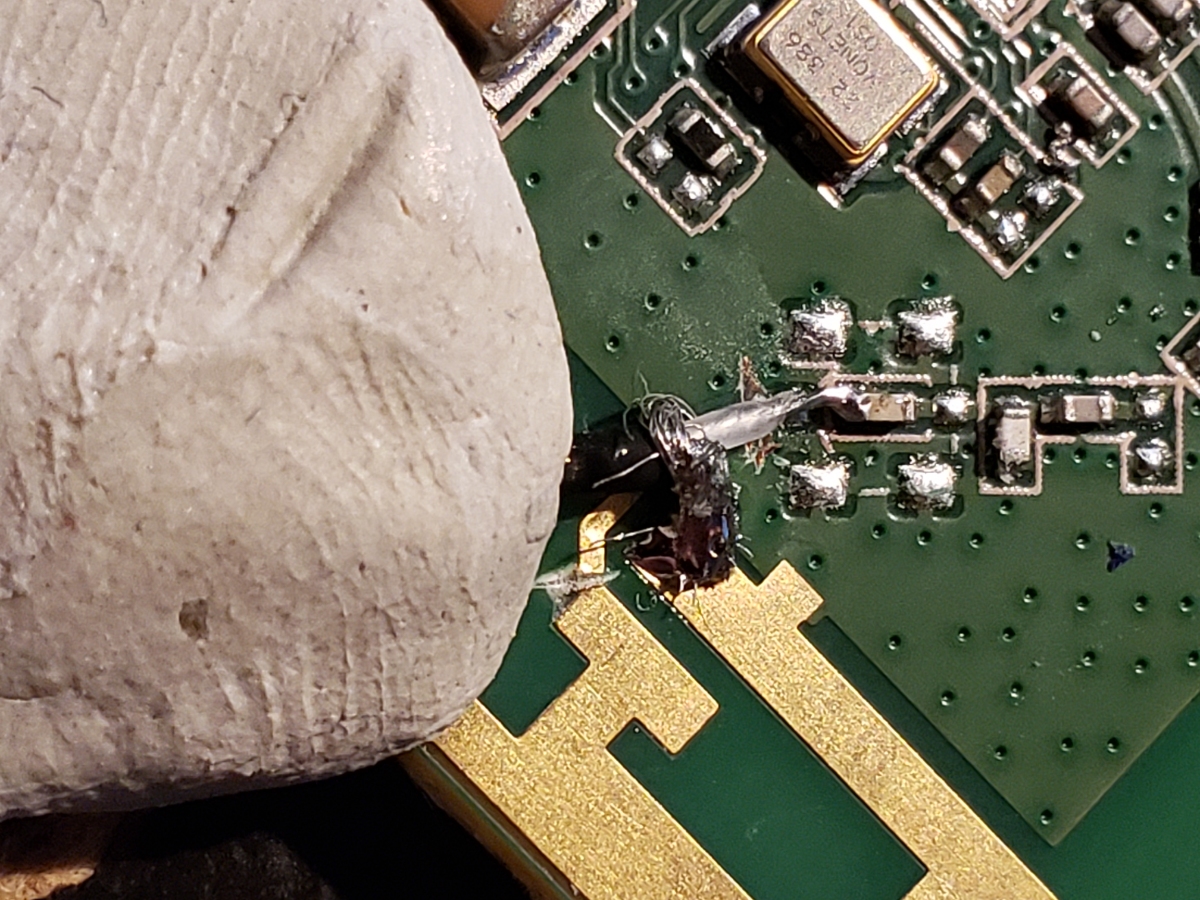
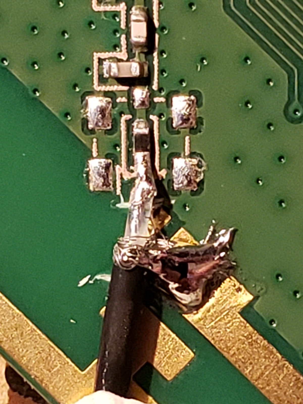
A bit of solder, and we’re connected. To give you a sense of minute scale, that’s my fingerprint in the sticky tack. These are all very small 0402 components.
You can see where this capacitor is located, there is an empty footprint for a U.FL connector. I could have hot-air reflowed a U.FL connector onto the board but it can be just as hard or harder to get four layer PCBs hot enough to rework a new connector on. Stripping and soldering was easier.
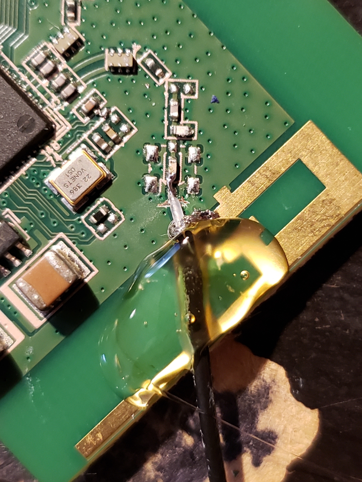
A blob of hot glue for mechanical reinforcement and we’re down one, with one to go!
Sticky tack. Sticky tack. 2nd RF path.
And we’re soldered! Note the fine hairs coming from the ground sheath. Before turning on the board I did a continuity test between the RF connection and GND to confirm there were no shorts.
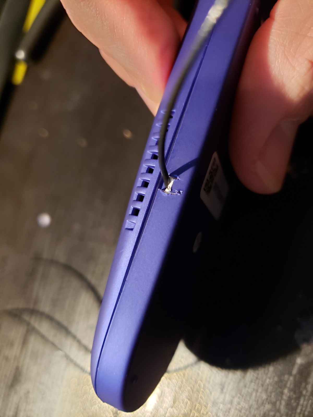
A quick and dirty enclosure modification allowed the thin RF cables to exit their respective sides of the enclosure.
It’s an ethernet WiFi bridge with aftermarket external antennas!
Above I’ve got the two antennas located and taped within the infographic areas. These are the areas that are covered by the paper and plastic describing how to use the phone. The infographics will cover the antennas while still allowing good RF reception.
Front face attached showing where the antennas sit.
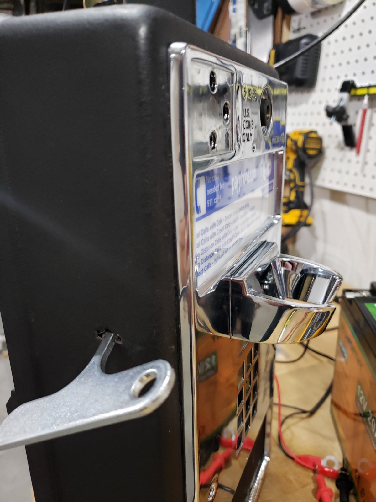
Above you can see the antennas protrude so little that even a very astute user would be hard pressed to detect them.
With the antennas located outside the enclosure, we gave it a try. A few field tests proved we’d get WiFi and VOIP access to our friend’s WiFi AP.
Coin Detection
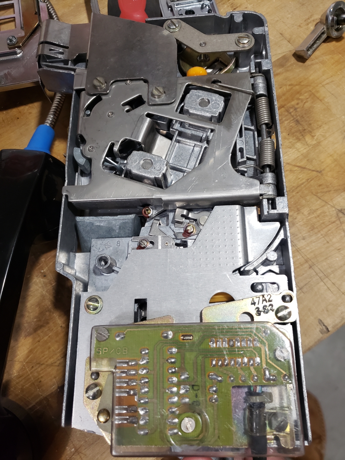
It’s hard to describe the incredible design that is a payphone coin validator. Imagine the challenge: without the use of electricity, correctly detect if a coin is valid or fake, then sort the coin into three chutes. And if the user shoves a penny, dollar coin, or shaved down cough drop, gracefully handle it and keep working for years without maintenance. I’m sure it took decades to arrive at some of these minutely counterbalanced trap doors, magnets, and chutes, but it’s just wonderful and satisfying to watch it work.
There should be a semester’s long mechanical engineering course that does nothing but take apart and analyze how a payphone coin validator works.

As Tim Hunkin (of the The Secret Life of Machines) used to say about his nickel arcade:
“If a user steps up to an arcade machine that’s free to play, they just start mashing buttons and walk away bored. If the user is required to put in even a trivial amount of money, they will stop to read the instructions and have a much better experience even though it cost them more.”
(Source: This is my memory of Tim speaking at the 2nd Maker Faire in 2007)
If you need to stop reading and go watch 'The Lift' episode, I won't fault you. It's just a really good show.
I don’t care what the user pays, I just want them to enjoy the experience. Said ludicrously differently: Anyone can call anywhere in the world for free, I think I shall charge them a nickel!
My wife and I originally planned the payphone to accept any coin denomination, from any country. But because of my limited mechanical engineering we decided it was a better trade off to leverage the existing coin validator.
The coin validator will eject anything that is not a nickel, dime, or quarter. Validated coins then pass a small circuit board (shown above) that is effectively a small metal detector. The IC part # is Motorola KS21625L7 14050122B.
The back of the coin acceptor PCB allows us to quickly figure out power and ground and where the individual coin signals are coming from.
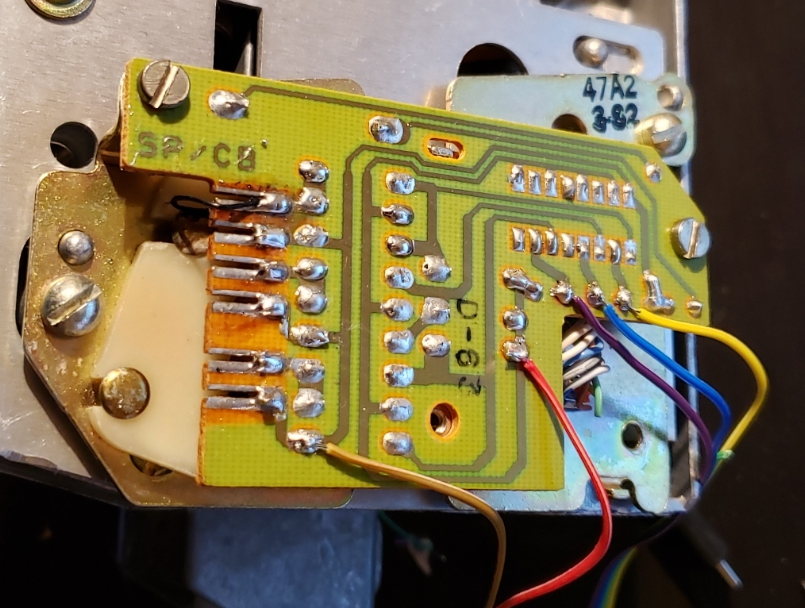
In the above photo we've successfully hijacked the coin validator:
- Brown: Ground from Arduino
- Red: 5V from Arduino
- Purple: Dime - Pin 10 on Arduino
- Blue: Nickel - Pin 9 on Arduino
- Yellow: Quarter - Pin 8 on Arduino
With a bit of work, and Nico Hood’s PinChangeInterrupt library, I successfully triggered a falling edge interrupt anytime a coin passed.
Number Detection
As mentioned above, the keypad has a DTMF encoder IC built-in so I needed a way to decode the DTMF tones in order to detect what number was being dialed. There was a variety of ways of doing this including a dedicated DTMF decoder, but why not use the Arduino itself?
From the AMI S2559E/F IC datasheet we know where the power, ground, and audio out pins are located. Powering the IC with 5V and sending the audio signal into an Arduino pin was easy enough. An inline 1uF capacitor was used to block any DC current. But how to convert the frequency into a number? Enter Goertzel. I’ll let Jacob Brosenthal, the creator of the Goertzel Arduino Library explain:
The Goertzel algorithm is long standing so see http://en.wikipedia.org/wiki/Goertzel_algorithm for a full description. It is often used in DTMF tone detection as an alternative to the Fast Fourier Transform because it is quick with low overhead because it is only searching for a single frequency rather than showing the occurrence of all frequencies.
We know the keypad is going to generate only the following 8 frequencies:
- 697
- 770
- 852
- 941
- 1209
- 1336
- 1477
- 1633
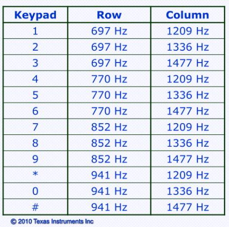
Image credit: Texas Instruments - ‘Practical Audio Experiments using the TMS320C5505 USB Stick’
We can set up two loops called ‘row’ and ‘column’. For example, if we detect 852 and 1477Hz we know the user is pressing the ‘9’ button. There are some additional settings including the number of samples to take and the threshold that we must cross to indicate the presence of the frequency. For the purposes of the payphone project, these two settings (N and threshold) were stored in EEPROM and I used the very sophisticated approach of ‘try it till it works’ to establish the best values.
With Goertzel and the settings in place, the internal Arduino now knew what number was being pressed. From there, I used a state machine to establish if the user was dialing an allowed series of numbers (ie 9 - 1 - 1) or a disallowed series of numbers (ie 6 - 0 -... would force the user into the ‘Please deposit a coin’ path).
What numbers should be allowed without requiring a coin payment?
Toll Free Numbers

In the USA, most people born before 1999 know what a '1-800' number is. For those who don't: a number that started with 1-800 was a 'toll free' number; a phone number where the calling fees are charged to the business who has the number. For example, 1-800-736-0308 is the phone number to purchase a ShamWow. It's not 'long distance' (where charges are applied to your phone bill), it's toll free. This concept has mostly disappeared like TV Guides and merry go rounds. With cell phones there is no such thing as long distance so the necessity for toll free numbers has declined dramatically. However, toll free numbers were hugely popular in the 1980s and 1990s. As such, the phone companies had to add 1-888 as an additional toll free area code.
Pop quiz: is 822 a toll free area code? How about 844?
I didn't realize it until this project but there are a lot of toll free area codes. 800, 833, 844, 855, 866, 877, and 888 are toll free. So the Payphone Project passes any of these numbers through without the necessity of a coin.
911
My wife and I agreed that, jokes aside, if we’re going to put a phone on the street, it has to have working 911. Thankfully, there are services like CallCentric that, for $1.95 a month, will connect a number from Google voice to a physical location and enable 911 forwarding. If someone dials 911 from the Payphone Project, it immediately gets routed to the nearest call center with the phone's address information.
867-5309
While Tommy Tutone’s popularity peaked a bit before my time, I still have this number etched into my brain (yay popular culture).
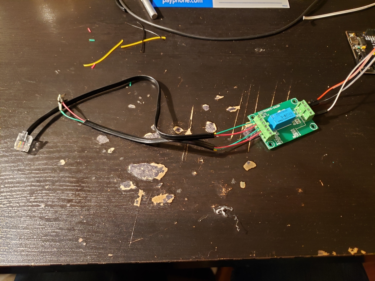
This relay is a single pull, double throw (SPDT) relay. This allows us to interrupt the phone line, effectively ‘hanging up’ the phone even though the user still has the phone in their hand.
If the user keys in 867-5309 we disconnect the phone from VOIP (turning off the call control relay mentioned above) and then connect the handset to our MP3 player, and begin playing our desired easter egg.
0

What to do when a user needs an operator? I considered forwarding the user to 1-855-LADYFUN (which is a whole, amazingly deep alternate reality game, that you must absolutely check out) but that was a bit too meta. Instead, I thought it would be more fun just to expose the poor user to an infinite loop of Strong Bad’s Hold Music. This is the operator easter egg:
303-284-0979
This is SparkFun’s main number in the ‘real world’. So of course you’re going to get Rick whether you put a coin in or not. Here’s our short clip:
Please Deposit A Coin
If the user enters a number that requires a coin, they are disconnected from VOIP and we play our final ‘easter egg’. It’s the classic ‘This call requires a coin deposit’ operator prompt combined with Aloe Blacc’s I Need a Dollar. You can hear the combined clip below:
MP3 Injection
In order to play our various easter eggs, we needed the ability to easily play MP3s, but more importantly we needed to hijack the handset. So a 2nd SPDT relay was added. This relay sits between the handset earpiece and the hook switch board. We can either connect the ear piece to the phone’s mainboard like a normal phone would be connected, or we can switch the relay and connect the MP3 output to the handset earpiece. This gives us man-in-the-middle control of what the user hears.
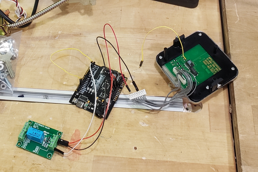
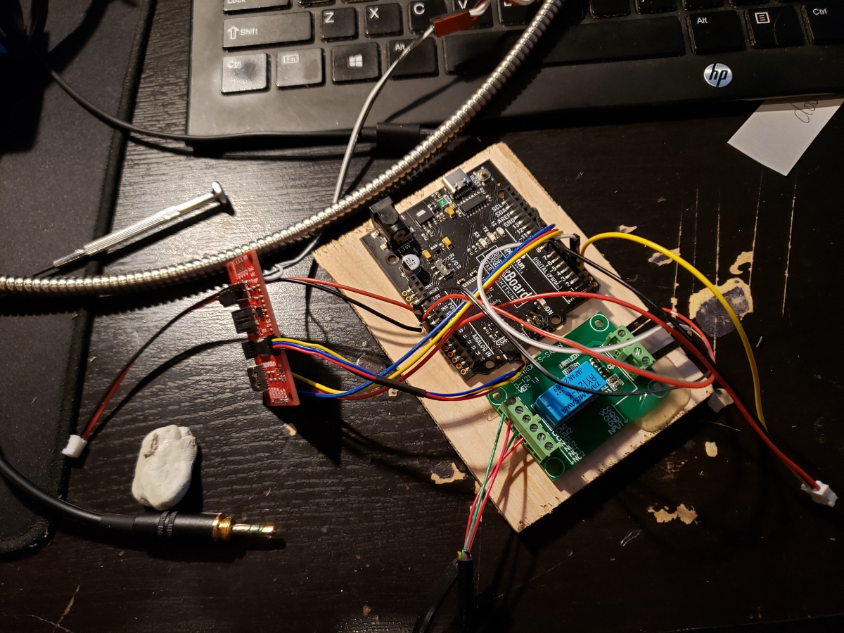
Bench Testing
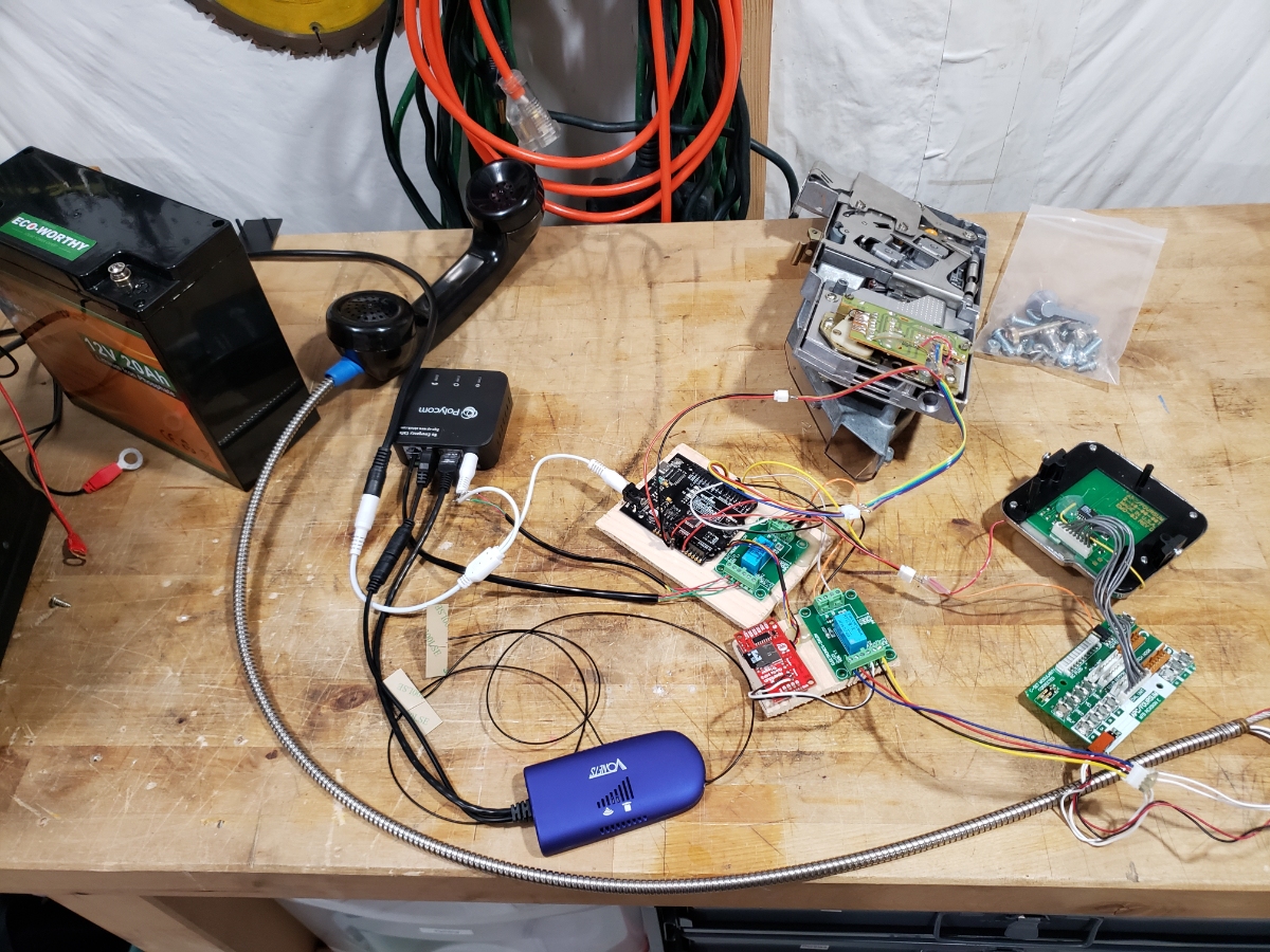
It lives!
In the end we have 8 pins to deal with via software:
- Analog pin for DTMF decoding
- GPIO for hook detection
- GPIO for VOIP call control
- GPIO for handset earpiece control
- GPIO x 3 for coin detection
- Qwiic connect to MP3 player
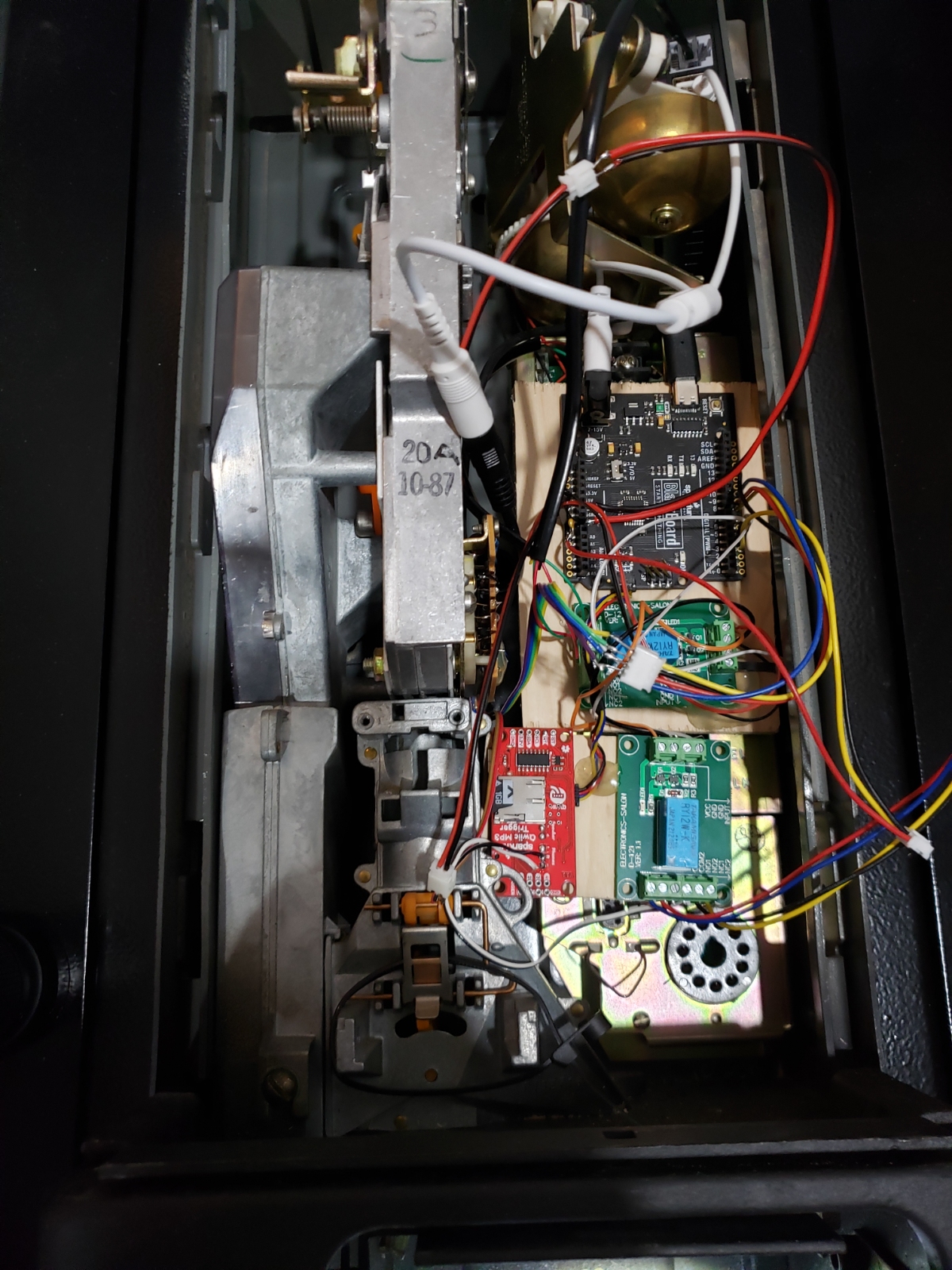
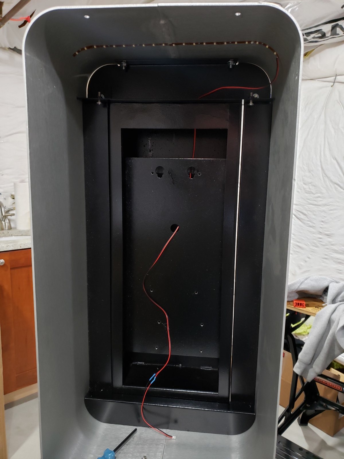
Here is everything placed inside the main housing. Some wood backboard with magnets glued on allowed the mess to be easily installed or removed.
Above is inside the front face. You can see the large metal ‘coin return’ armature as well as the blue WiFi ethernet bridge. Down below you can see a few connectors with hot glue.
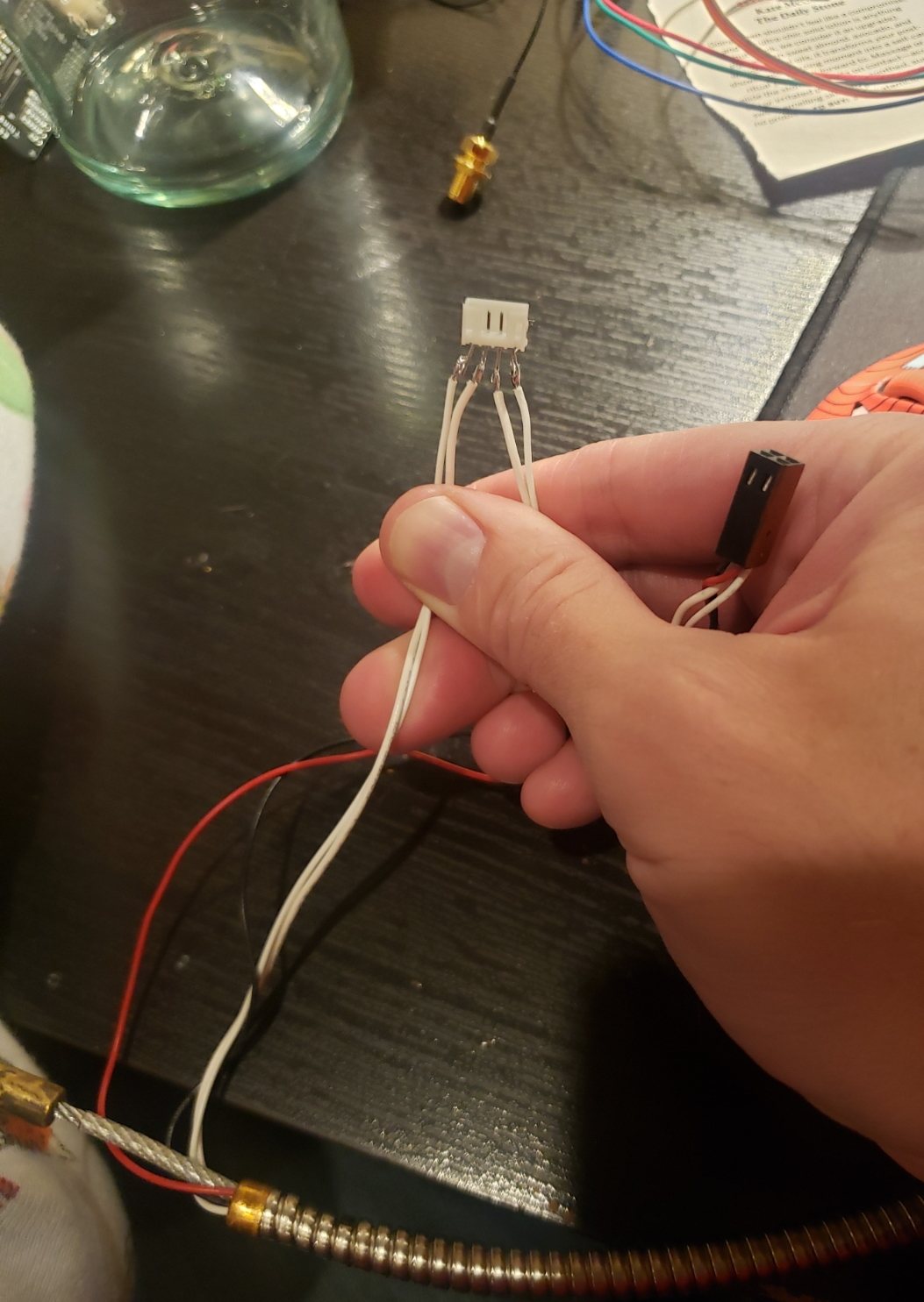
There were a few connections between the front face enclosure and the main housing. Normally these are contained in the single 11 pin circular connector but we needed 8 additional pins: 4 for earpiece man-in-the-middle, 3 for DTMF decoding, and 1 for detecting when the phone was on the hook. In order to allow the front face to be fully removed I soldered mating JST cable sets and reinforced and electrically isolated the connections with hot glue. In the above photo you can see the interruption of the handset earpiece wires.
Power
Seen on the left is a LiFePO4 lithium iron phosphate battery. This new battery chemistry is a bit less energy dense than a lithium ion battery, but LiFePO4s cannot achieve thermal runaway. Said differently, these batteries don’t go kablooey if something goes wrong. I’ve had a few LiPos puff on me before and given the harsh outside, public environment, LiFePO4s were a great choice. These new type of 12.8V batteries are dropping quickly in price. I picked up a couple 20Ahr sized batteries for $70 each.
The LiFePO4 12V batteries fit perfectly within the phone pedestal base.
The average standby current for the PayPhone Project was ~250mA with everything on: the VOIP Obihai device, the WiFi bridge, the overhead LEDs, relays, etc. With 20Ah we had a run time of about 80 hours. I set a calendar reminder and replaced the battery every 3 days and never had a power outage. In the future we could run two batteries in parallel (one stacked on the other inside the base) and get perhaps 10 days of run time with two 30Ah batteries.
Code
You can get the firmware on our github as well as a variety of test-out sketches from the repo.
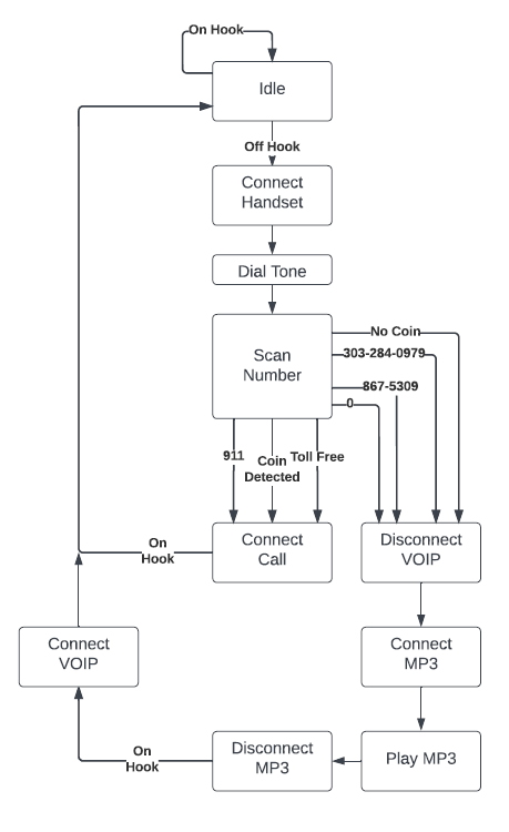
The firmware for the Payphone is fairly straight forward. We look for the user to lift the phone off the hook, then start tracking what number is dialed or if a coin is deposited. If a coin is deposited, allow the call to go through. If the number is allowed without a coin (ie, 911, 303-284-0979, etc) allow the call to go through. If there is no coin, and the phone number is not a 'free' type, then hang up the VOIP and connect the user to the 'Please deposit a coin' MP3.
Infographics
While electronics are important, the 970-HA-JOKES Payphone Project needed to look good for maximum giggles.
Ok, maybe we got a bit carried away, but it was COVID.
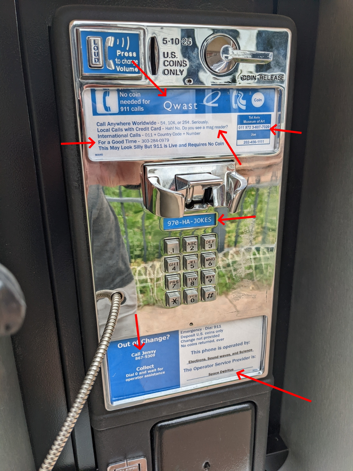
For anyone who has lived in Colorado for awhile, Qwest was the household name when it comes to telephone providers. Making this Qwast made sure to let anyone know this was not your normal payphone.
I knew we had done a good job when my neighbor asked how I felt about the phone company putting a payphone in our neighborhood. I had to explain to her that it was a joke project that I had built and as soon as she saw the Qwast logo, her laugh made it all worthwhile.
Yes you really can call internationally with a nickel. Yes, that is the museum of modern art in Tel Aviv. We specifically picked numbers that have a phone tree; jokes are fun but I don't want to bother actual humans.
Joe: That's the phone number for the White House. Okay maybe a human answers that number, but I pay taxes so at least they are paid for the hassle.
970-HA-JOKES or 970-425-6537 is the pay phone’s number. Thanks to things like Google Voice and tools like PhoneSpell we can quickly check an available number. When I saw ‘Ha Jokes’ was an available phone number, I knew we had a winner.
Flyer
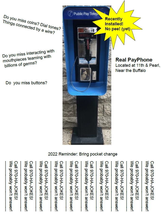
No pee! (yet)
Interactive projects are tricky. Most folks are suspicious and generally don’t want to mess with something unless it’s clearly stated. So of course we had to make up flyers, send them to friends, and post them around our neighborhood.
Statistics
My wife and I agreed at the onset that we didn’t want to record phone numbers or cameras recording people using the phone. But I did track and record the various interactions. The phone was deployed for about 10 days. I’m kind of surprised how many people actually had coins!
- Interactions: 406
- Free calls: 2
- Paid Calls: 47
- I need a dollar played: 49
- SparkFun called: 5
- Jenny called: 5
- 911 called: 1
- Coins obtained: 47
- Pounds lifted up a flight of stairs: 97
- Money made: -$1,055 for phone + $6.25 in coin deposits = -$1,048.75
After 10 days we decided we had enough fun and wanted to remove the phone before too many questions were asked. We returned the abandoned pad to its original state.
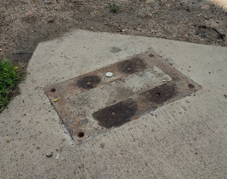
The following day a single nickel was left, placed perfectly on the pad, by someone. A payphone libation of sorts for all the removed and missed payphones out there.
The End
The project was a huge success. People who knew what was going on loved the experience. Our kids loved calling people and the looks people gave the phone ran the gamut of extreme suspicion to utter bliss. It was great fun!
The next time you see a payphone, stop and give it some attention. It’s always worth a look.
Moar Projects
Here are some additional fun/odd projects from SparkFun.
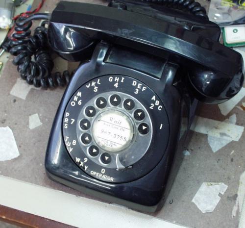
The SparkFun Rotary Cell Phone

The original SparkFun Free Day


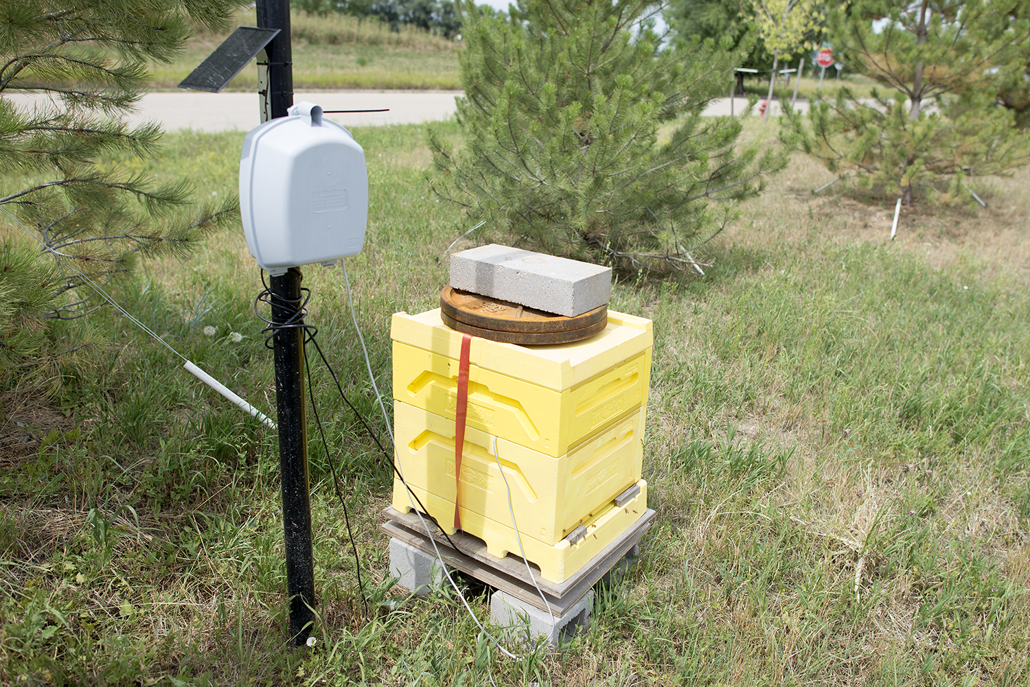
Measuring the weight of a bee hive over time
Other random Nate posts