THAT InGenius and OutSmarts Breakout Hookup Guide
 Byron J.
Hardware Overview
The THAT InGenius and OutSmarts integrated circuit families implement high quality balanced input and output amplifiers with a minimum of external components. The circuit topologies were invented by Bill Whitlock, the President and Chief Engineer of Jensen Transformers. Mr. Whitlock is also a recognized expert on audio interfacing, having published many papers and troubleshooting guides on the subject. They are manufactured by THAT Semiconductor, who specialize in high-quality analog audio ICs.
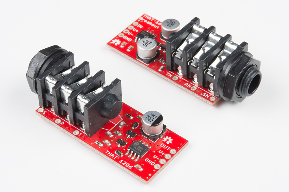
These two breakouts perform mirror-image signal conversion. The 1646 OutSmarts is a unbalanced-to-balanced output driver, and the 1206 InGenius is a balanced-to-unbalanced input receiver.

The breakout boards add passive components to support each IC, plus TRS jacks.
The circuits come from the THAT datasheets, and include the recommended RF filtering, DC offset reduction, and transient suppression networks.
THAT Breakout Boards
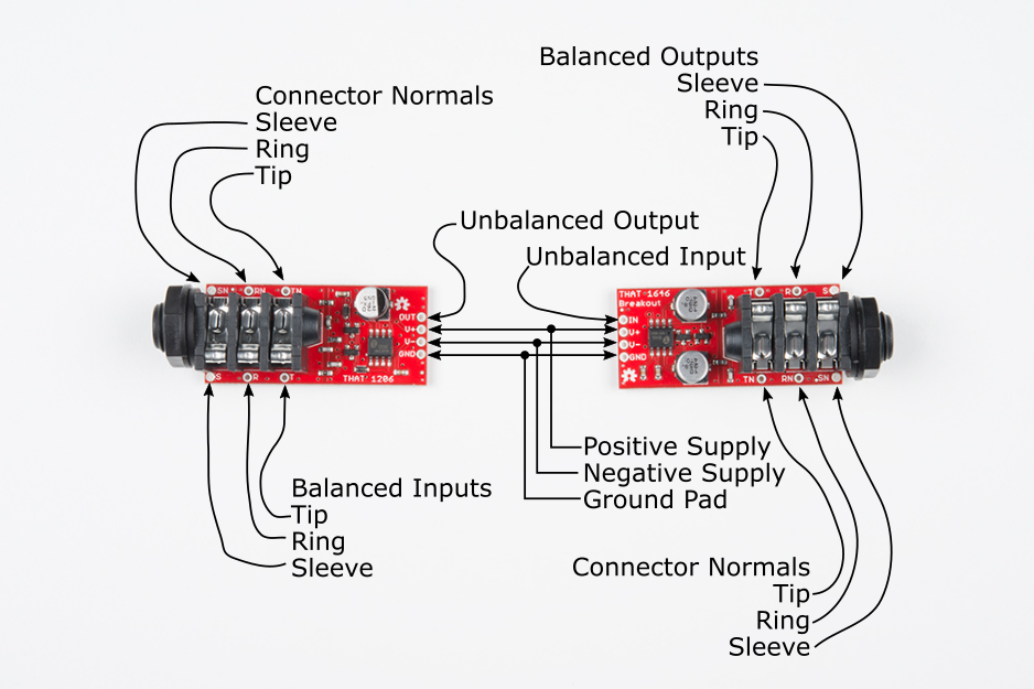
The external interface on each board (the output of the 1646 and the input of the 1206) is on a 1/4" TRS socket. The TRS is wired with the regular-polarity signal on the Tip, and the inverted signal on the Ring. Adjacent to each leg of the socket are test points for the signal (T, R, S) and normal (TN, RN, SN) contacts. When nothing is plugged into the socket, the normals connect to the corresponding signal pad. When a jack is plugged in, it connects to the signal pads, and the normals float.
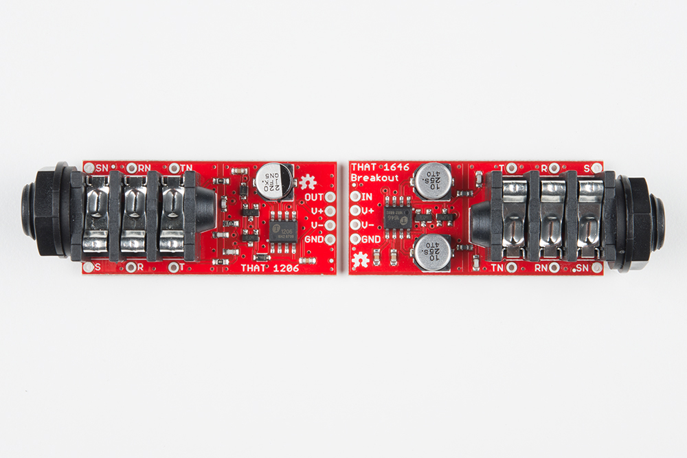
The internal connections are on four 0.1" header pads.
| Pad Label | Function |
|---|---|
| In | 1646 unbalanced input |
| Out | 1206 unbalanced output |
| V+ | Positive power supply rail |
| V- | Negative power supply rail |
| GND | Ground |
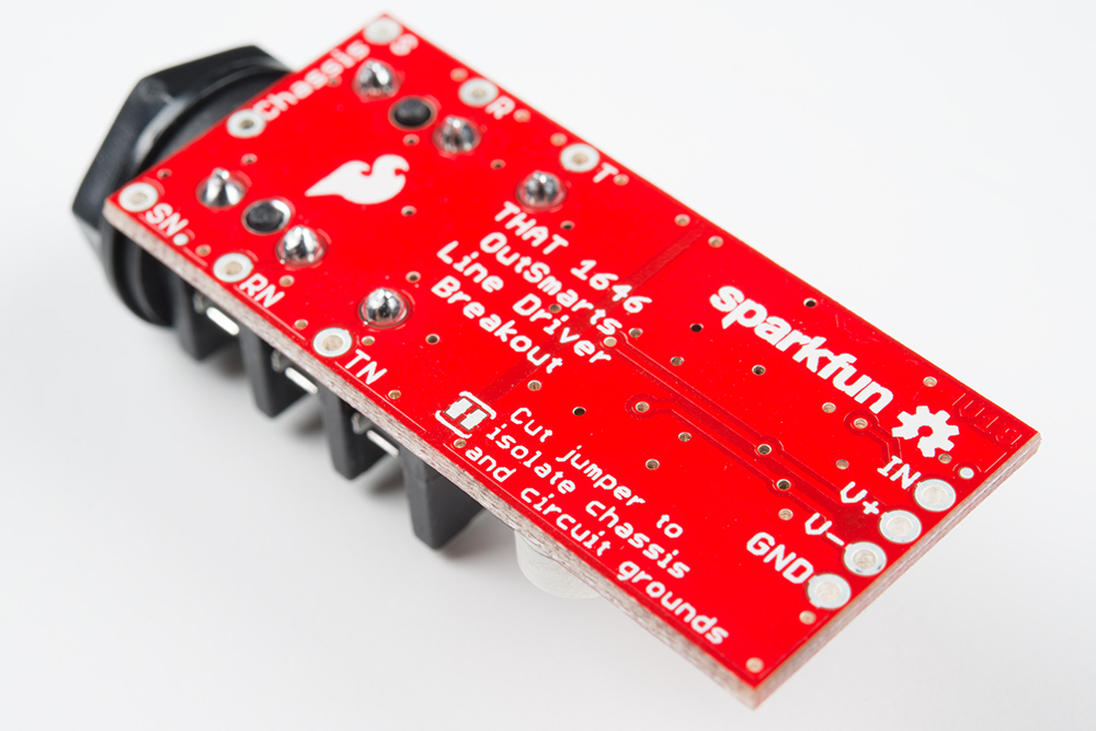
Grounding
There is a jumper on the back of the PCB that allows for two different grounding configurations.
By default, the board assumes a single ground connection through the 0.1" header. This is how you'd deploy these breakouts on a breadboard, or in a plastic enclosure.
However, if you have a grounded metal enclosure, it's considered bad practice to run the shield of the cable around inside the Faraday cage of the enclosure -- it creates an antenna within the cage that re-radiates any noise induced in the shield.
The solution to this is to tie the shield to the enclosure right at the connector. On these breakouts, there is a jumper to separate the connector from the circuit ground, and pads that allow for a short ground wire to run under the collar of the TRS.
We'll examine how these are applied in the example project below.
Power and Headroom
Before we build some circuits with the THAT breakouts, let's discuss how to power them, and what that means for headroom.
Analog audio circuits usually run from bipolar power supplies, meaning the supply provides two rails, of equal and opposite voltages. The THAT breakouts follow this convention, and function across a wide range of supply voltages, from +/-5V, to an absolute maximum of +/-20V.
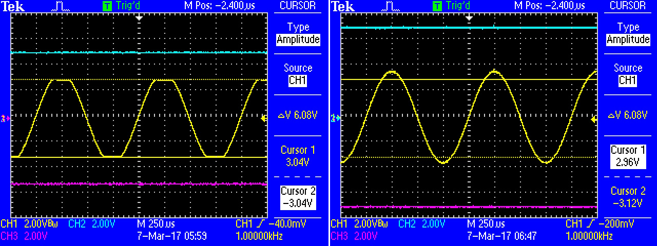
The power supply voltage determines how large a signal the IC can handle before clipping: for the THAT ICs, the clipping voltage is roughly 2 V below the supply rails. For example, running on +/- 12V rails, the ICs can handle 20 Vpeak-to-peak signals, which swing between -10V and 10V. If the signal exceeds that range, it will clip, resulting in distortion.
As the supply voltage changes, the point at which the IC clips move correspondingly. Typical pro-audio devices run on +/-15V to +/-17V supplies, while consumer hi-fi devices frequently have +/- 12V supply rails.
Finally, there is a bit of cleverness at play with the maximum signal levels from these ICs. The 6 in the name of each IC refers to how much gain or attenuation is applied to the signals they pass: 6 dB. The 1646 drives each leg of the balanced output with a signal that is as strong as the input -- the differential voltage is double the input voltage, or 6 dB hotter. The 1206 does the reverse: it cuts the input voltages in half (-6 dB) -- its unbalanced output is the same amplitude as either of the input legs.
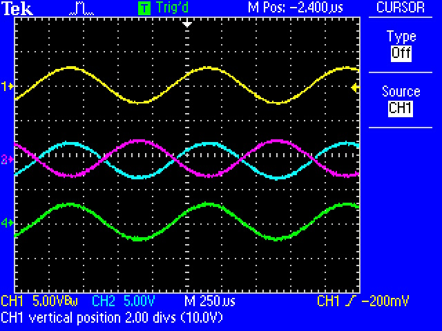
If you daisychain a 1646 into a 1206, the output of the 1206 will be equal to the input to the 1646.