THAT InGenius and OutSmarts Breakout Hookup Guide
 Byron J.
Example Application
Next, let's take our newfound skills with these breakouts, and use them to retrofit balanced outputs onto a device that doesn't have them already.
The candidate device is a Sony hi-fi component CD player. From the factory, it only had RCA jack outputs, but we're going to augment them with balanced TRS outputs, using a pair of THAT 1646 OutSmarts breakout boards.
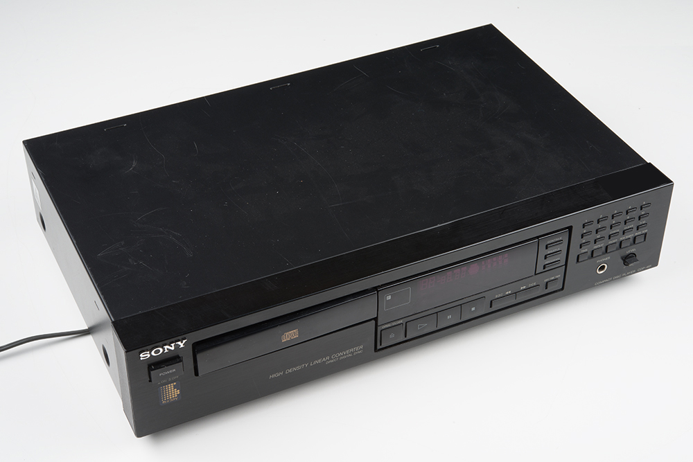
This particular unit was selected for a couple of specific reasons.
- First, it was working to begin with -- it's easier to add a feature to something that's already working, than to have to start with troubleshooting and repair work.
- Second, as a stereo component, it's in a reasonably large chassis, with plenty of room inside for the added components. There simply wouldn't be room inside for more components in a Discman-style portable player.
- Finally, it's a little older -- there's a sticker on the back panel indicating it was manufactured in 1991. That means that the components inside larger and less highly integrated, making it a little easier to accomplish the retrofit.
First step: Analysis
To add the THAT 1646 breakouts to this player, we needed to know several things:
- First, we need to find a place to mount them, where they won't cause problems with the inner workings of the player.
- Second, we need to identify the power supply rails in the player, and figure out how to power the breakouts. We're operating under the assumption that there will be a bipolar power supply that we can tap into.
- Finally, we need to figure out where we can tap the audio outputs, and verify that the signal we're extracting meets the 1646's allowable headroom levels
Mechanical Analysis
Finding a place to mount the breakouts was as simple as undoing the four screws to remove the top of the player. With the top off, it's apparent that the chassis is mostly empty space, and there's plenty of room for added circuitry.
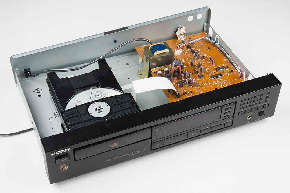
We opted to mount the breakouts to the back panel, next to the existing RCA jacks. The breakouts will be mounted using the nuts on the TRS jacks.
Power Supply Analysis
We then needed to figure out how to power the breakouts. We know each board draws about 5 mA from each power supply rail, and can function on supplies from +/-5 to +/- 20 VDC.
Looking in the player, there are a number of labeled wire jumpers on the PCB. In particular, there were jumpers labeled +5V, -5V, +10V, -10V and GND. +/- 10V sounds like a good starting point for the 1646, leaving plenty of headroom, but more careful inspection contradicted that thinking!
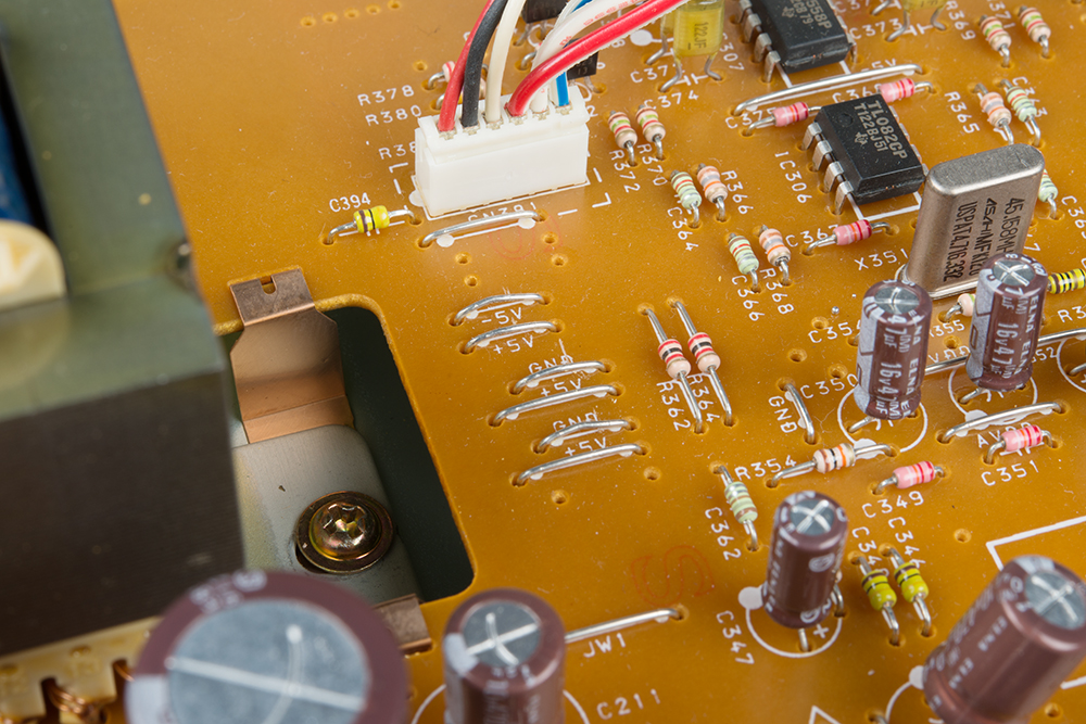
Just inside the RCA jack are the player's output stages, a pair of TL082 op amps, which were powered from the +/- 5V rails. A little more careful inspection with the oscilloscope revealed what was going on. The 10V lines are the raw output from the bridge rectifiers, and exhibit 60 Hz ripple. The 5V lines are the output of an M5209P voltage regulator, with no visible ripple.
Signal and Headroom Analysis
It was easy to find the output signals. Near the RCA jacks are a pair of wire jumpers, clearly labeled L and R. Those jumpers measure continuous with the tips of the RCA jacks.
To evaluate the headroom required, we burned a CDr with full amplitude sine wave test signals. Playing those tracks resulted in output amplitude of 5.6 Vpp, and we verified this as several frequencies across the audio spectrum.
The 5.6 Vpp level just happens to dovetail with the headroom that we measured on the breadboard. Powered from +/- 5V, the 1646 can handle input signals up 6 Vpp.
Putting It All Together
Materials
Aside from the CD player, we needed the 1646 breakout boards and some hookup wire.
We also used a drill press with a set of graduated metal bits, cutting oil, and soldering tools including an iron and wire strippers.
Mounting The Breakouts
The rear panel comes completely off the back of the unit, which allowed us to drill holes to mount the breakouts without being concerned about metal chips falling into the rest of the unit. Since the panel and chassis are metal, we cut the shield jumper on the bottom of the board, and soldered a loop of stranded hookup wire to the ground pad.
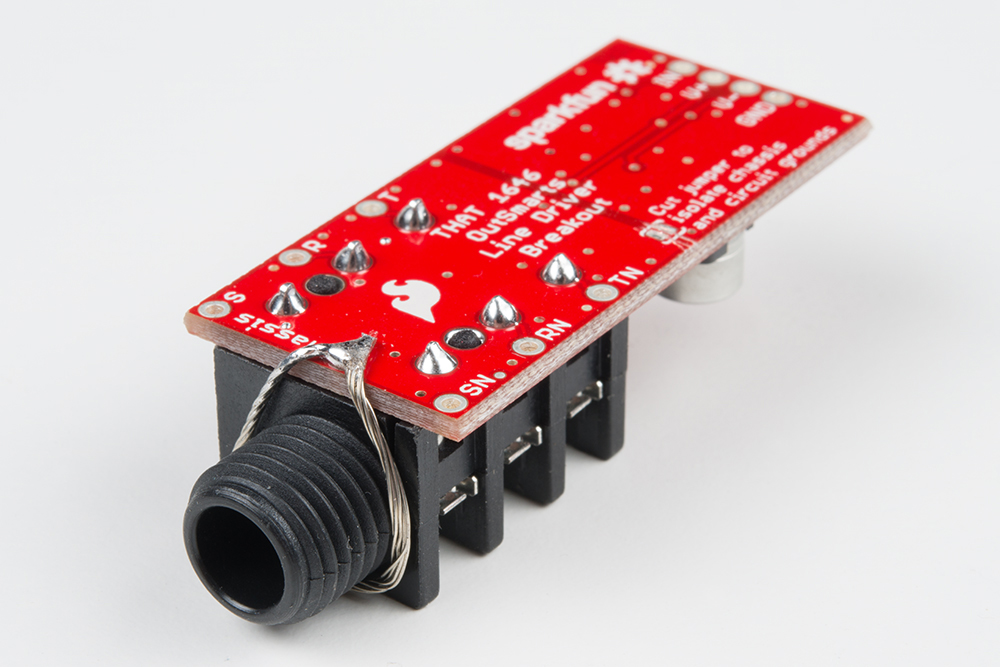
When the breakout is mounted in the panel, the loop makes contact with the chassis.

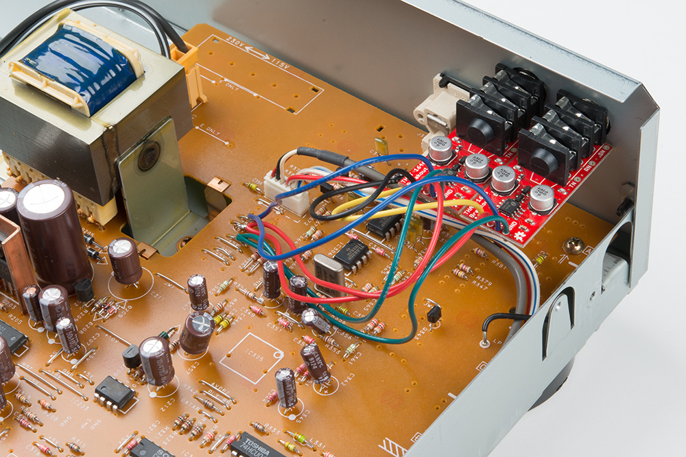
We then ran some short pieces of stranded wire to the points identified in the analysis. The wiring went like this:
| Wire color | Connection in CD player | Point on breakouts |
|---|---|---|
| Red | +5V | V+ (both boards) |
| Green | GND | GND (both boards) |
| Blue | -5V | V- (both boards) |
| Yellow | L | IN (Left board) |
| Black | R | IN (Right board) |
Each board got it's own power wires; the far ends of those wires were twisted together, and tack soldered to the corresponding points on the CD player board.
With everything assembled, it's time to test it out, then close the player back up!