THAT InGenius and OutSmarts Breakout Hookup Guide
 Byron J.
Breadboard Experiments
To get started with these boards, lets build a few circuits on a breadboard, and observe their performance on an oscilloscope. You'll need the materials listed above, in the required materials section.
You'll also need a bipolar power supply, signal generator, and an oscilloscope to follow along.
Balanced Output With 1646
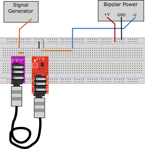
First, we'll convert the unbalanced output of our signal generator into a balanced output, using the 1646 breakout.
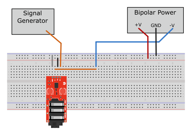
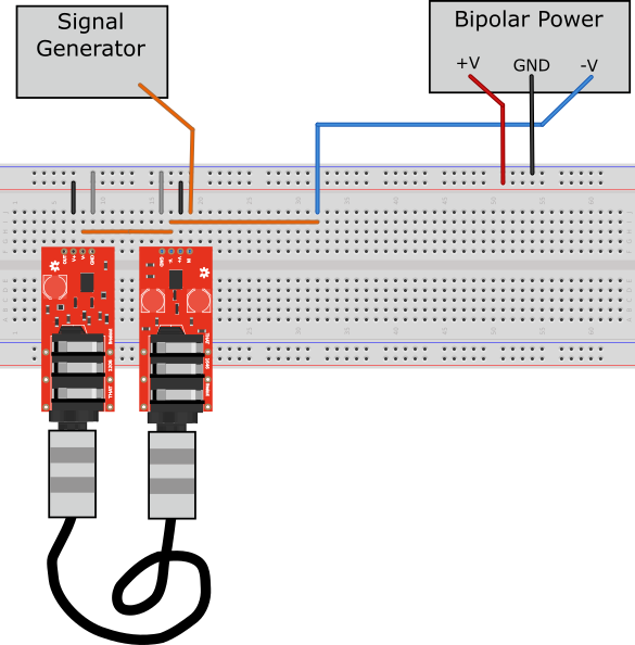
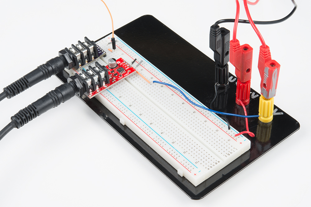
We assembled the circuit on a solderless breadboard. Because we're using a bipolar power supply, we had to run three wires (V+, ground and V-) from the power supply. We also connected the output of our signal generator to the input of the breakout.
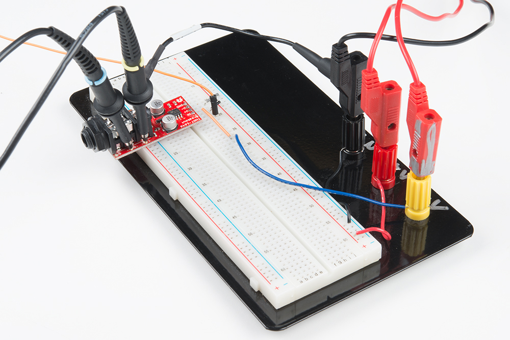
With the generator, adjustable power supply, and oscilloscope, we can evaluate the behavior of the 1646.
Set the signal generator to produce a 1 kHz sine wave at 5 Vpp, and set the power rails to +/- 12V. Then switch the power supply on, and use the oscilloscope to observe the signals at various points in the circuit, as discussed below:
- The breakout draws about 5 mA from each supply rail. If the draw is higher than that, switch the supply off and double check your wiring.
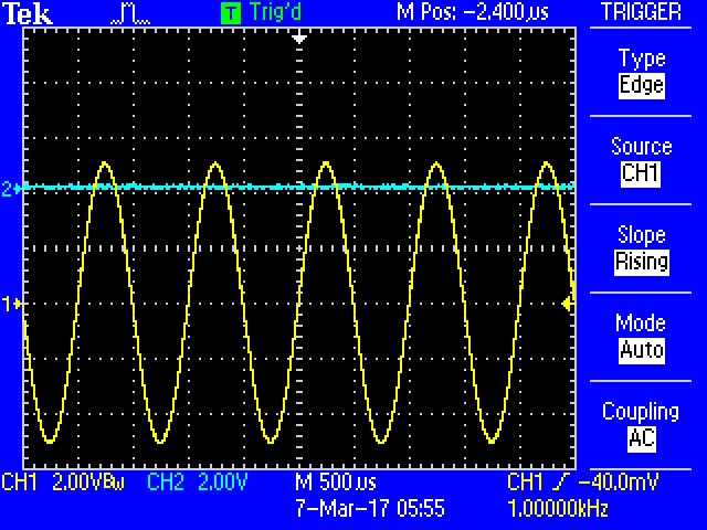
- Probe the signal generator output and Tip of the TRS connector: the signal polarity and amplitude are identical.
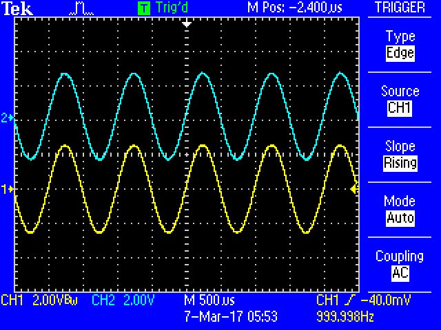
- Compare Tip and Ring outputs: they should be same amplitude, but with opposite polarity.
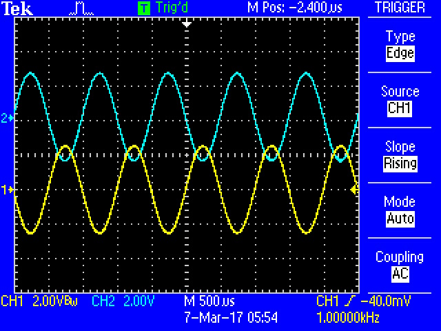
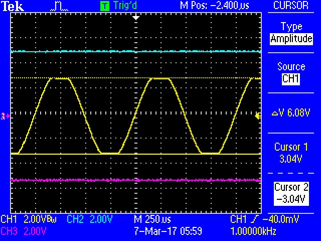
- Keeping the probes on the Tip and Ring outputs, short the ring connection to ground (we used a snip of wire to bridge the ring to the sleeve). The voltage observed at the tip doubles to 10 Vpp, and the ring goes to 0V. The 1646 keeps the differential amplitude the same (10V - 0V is equivalent to (5V - (-5V)) ), and the 1646 still exhibits 6dB gain. The supply current remains at 5 mA per rail.
- Finally, let's check the clipping amplitude of the 1646. Reduce the supply rails to +/- 5V, then increase the generator amplitude while monitoring the output signal. The output will start to clip when the generator reaches 6 Vpp. Once you see the clipping, increase the supply rails slightly, and notice that the clipping point tracks the rails.
Balanced Input With 1206.
Moving on, we'll add a 1206 breakout to the circuit we built above.
We plugged them together with a TRS cable.

Checking the behavior of the circuit with the oscilloscope, we observe:
The 1206
OUTpin matches the original input.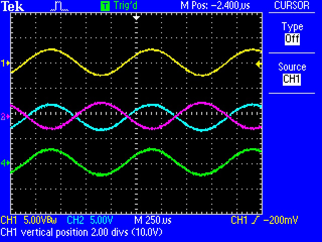
- As with the previous experiment, shorting one leg of the interconnection to ground results in no change to received amplitude.
Common Mode Rejection Test
As illustrated in Figure 5 of the 1206 datasheet, we can test common mode rejection by applying the same output from a signal generator to the Tip and Ring of the 1206 input connector, and observe the output with an oscilloscope.
To make the connection a little easier, we used a TRS breakout board, and connected it's T and R pads with a wire on the breadboard. Then we ran a TRS cable from the TRS breakout to the THAT 1206 board.
Set the signal generator for a 1 kHz sine wave, and slowly increase the signal generator amplitude, while keeping an eye on the board output. The output will be extremely small when compared to the input. On our test system, we applied 5 Vpp and could not measure any significant signal at the output -- the scope's finest input range is 20 mV per division. THAT state the 1206's CMRR as better than 90 dB, which translates an algebraic factor of about 32,000.
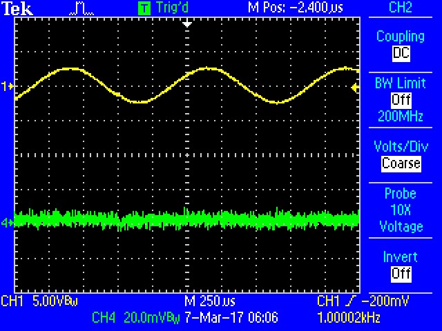
Notice that the output scale is 20 mV per division.
By adjusting the generator frequency, we can observe that the CMRR is similar across the audio spectrum, from 20 Hz to 20 kHz.