THAT InGenius and OutSmarts Breakout Hookup Guide
 Byron J.
Background
Before we look more closely at the THAT breakout boards, let's explore what they're used for: driving and receiving differential (AKA balanced or double-ended) signals.
Signaling Model
A typical model for analog electronic commmunication involves a transmitting device, which sends signals to a receiving device. In between, they're connected with a conductor: traces on the printed circuit board, or wire between the devices.

In a simplistic approach to analog signaling, the transmitter simply puts voltage on the line, and the receiver observes that voltage.

Sometimes, the connection runs through a less-than-ideal electronic environment. It could pick up additional unwanted voltage from sources along it's path. In signaling theory, unwanted signals are known as noise. Sources of noise could include digital signals on the same PCB, or nearby radio or electromagnetic equipment.

In these cases, the receiver receives the combination of the original signal, plus the noise picked up along the way.
Differential Signals
Differential signals use a bit of clever algebra to achieve noise cancellation.
The output generates two signals, one in original polarity (known as the hot leg), the other inverted (the cold leg).

The receiver subtracts them from each other, to restore the original signal.

Any noise picked up along the way will be the same on both signals. When they're subtracted, the inverse polarity signal is reinforced, but the noise is canceled! N - N = 0!

Differential signaling takes advantage of the principle of common mode rejection. When the signals are subtracted, anything that they have in common gets canceled. The degree of common mode rejection achieved is typically expressed in decibels, known as the common mode rejection ratio, abbreviated CMRR.
The Difference between Differential and Balanced?
In this hookup guide, we're specifically talking about the analog audio application of differential signaling. In audio literature, this is usually referred to as balanced interfacing. It's a problem-domain specific term, used to describe the more general principle of differential signaling.
Differential signaling is not limited to audio or analog interfacing. A modern computer is full of differential digital interfaces: USB, LVDS RAM, displayport, and SATA all use variants of differential digital signals.
Balanced Signals In Audio Systems
Any audio system involves devices that employ a wide number of connectors and signaling standards. To properly connect everything, you need not only an understanding of the different connectors being used, but also the circuits behind them! The following table summarizes some of the possibilities.
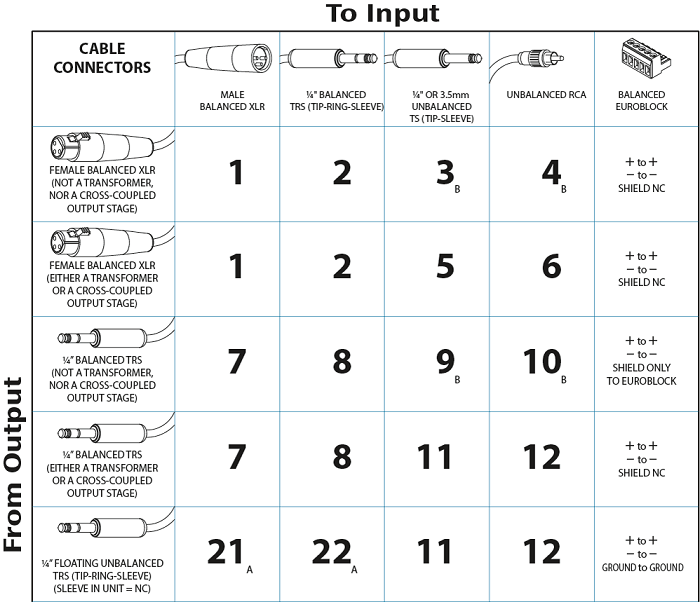
There are some particular pitfalls what await in the audio interfacing world.
- 1/4" TS and TRS sockets look the same from outside, but aren't functionally equivalent.
- TRS jacks are used for balanced outputs, headphone connectors, and insert-point connections. The connector is the same, but they're not compatible with each other.
- There's no guarantee that an XLR is actually balanced. There have been devices that left a pin disconnected!
- There was also a period of disagreement as to which pin on an XLR was hot. Today things have mostly settled on pin 2 being hot, but if you're having problems, you might have a pin-3 hot device.
- No matter how carefully selected the equipment is, Murphy's Law dictates there will be one essential piece of unbalanced equipment.
With some equipment, you're lucky, and the interfacing details are printed near the connector in question. Other times, they're described in the users manual, and sometimes you're left to figure it out on your own!
Sometimes, just using the right combination of connectors or adapters gets things into decent shape. Other times, it might be easier to modify or retrofit a better input or output stage...