TFT LCD Breakout 1.8in 128x160 Hookup Guide
 Liquid Soulder
Hardware Overview
TFT LCD Module (KWH018ST01)
The TFT module is the heart of this product -- it contains all the subsystems that are required to make an image show up. Starting with one of the most obvious features; the LCD screen is a glass panel with small little cells of liquid crystal (LC) material that can be shifted from opaque to clear with an electronic signal (more on how LCDs work). For each of the 128x160 pixels in the screen there are three LC cells and each cell has either a red, green, or blue filter in it to color the light. A pixel gets colored when white light from the LED backlight passes through the filtered cells in varying amounts.
The amount of light passed through is controlled by the signal applied to the liquid crystal cells, but the sheer number of pins and complexity of those signals is totally impractical to control directly with a microcontroller. Fortunately some really smart cookies created a dedicated driver Integrated Circuit (IC) that stores pixel data and puts it on the screen for us. Connections to the driver, as well as the backlight, are broken out along a flexible flat printed circuit (FPC) cable - and that's where we take over.
FPC Connector
The FPC connector is convenient for two reasons. First, it's extremely simple to (re)connect the display to the breakout board. Second, production of this product is made easier because all soldering can be done in our normal surface mount process.

To disconnect the TFT module just flip up the black locking bar with a finger or pair of tweezers and then gently pull the cable straight out from the connector. To put the cable back in, first make sure that the polarity indicators on the cable (1, 40) match up with those on the board and that the black locking bar is flipped up. Next push the cable in evenly for about 2mm.
Click on any of the below images for a closer look at what's going on:
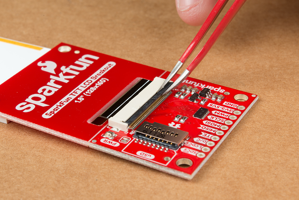 |
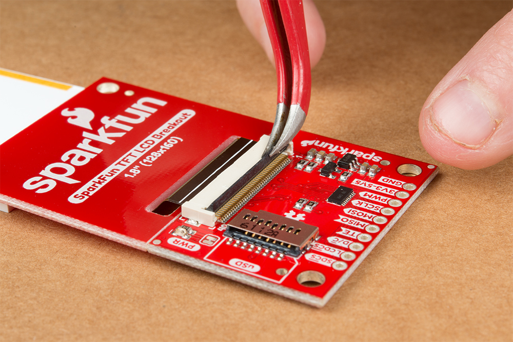 |
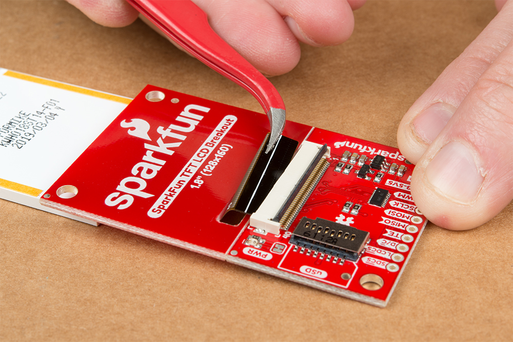 |
| Grasp Black Locking Bar | Lift Black Locking Bar Up | Gently Pull TFT Connector Out |
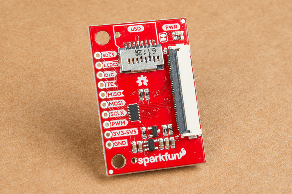
microSD Card Holder
The microSD card holder is there to relieve your microcontroller's poor memory due to having to store hundreds of images of cats, or really whatever you want to keep there. The SD card is connected to the same SPI bus as the display, which in turn keeps the required pin count low.

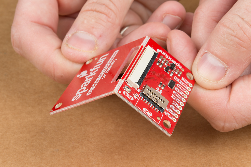
Breakaway Panel
Out of the box, the TFT will come with a large backing PCB that makes it easy to securely mount the display in a project. If you need a more flexible solution you can remove the display module, snap off half the backing board, and then re-insert the display module. When this is done you'll be left with the bare minimum frame around the display to more seamlessly integrate with your project.
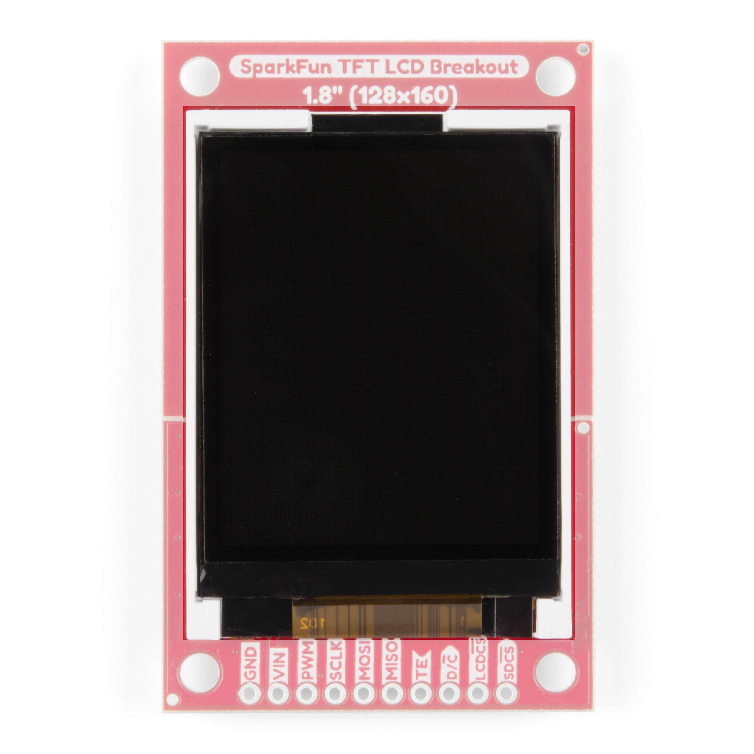
Pinout
The pinout of this breakout includes the standard SPI interfaces for both the TFT and the microSD card as well as a few specialty pins. You can power the breakout with either 5V or 3.3V thanks to the onboard voltage regulator and level shifter.
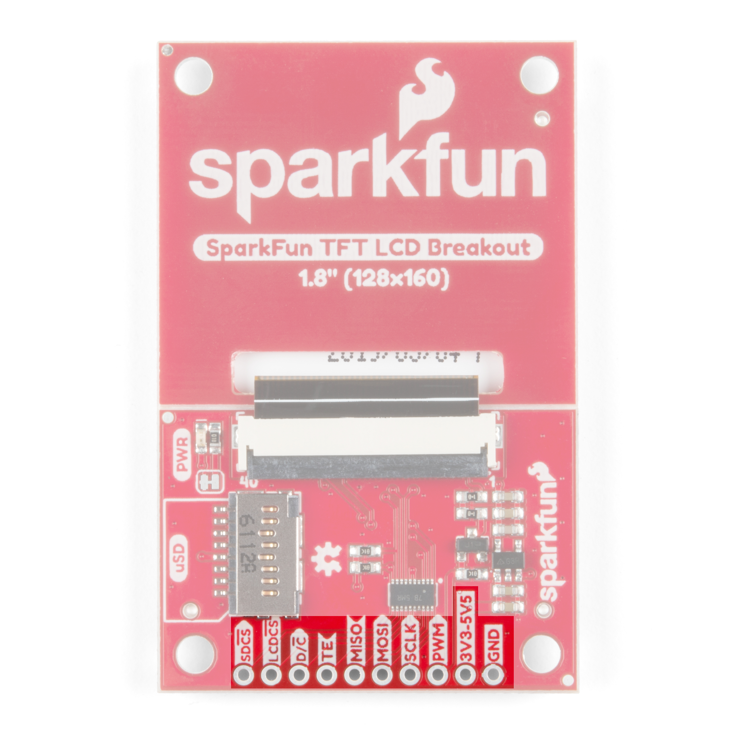
- SDCS : The microSD card chip select, pull this pin low to talk to the microSD card
- LCDCS : Chip select for the display, pull it low to talk to the TFT module
- D/C : This is a special signal found in many display controllers. When it is high the incoming data is interpreted as data as opposed to commands when it is low.
- TE : Tearing Effect is an optional output from the display to synchronize data writes - to avoid the 'Tearing Effect' that is seen when data is changed halfway through a screen refresh
- MISO : On this line the microSD card sends data back to the uC
- MOSI : The uC uses this line to send data into the TFT or microSD
- SCLK : Provides synchronization, but rates of up to 32 MHz are possible
- PWM : MOSFET input that allows a PWM signal to dim the backlight
- 3V3-5V5 : Since the breakout has a voltage regulator and level shifter built in you can use it with either of these two popular voltages.
- GND : It is important to stay grounded!
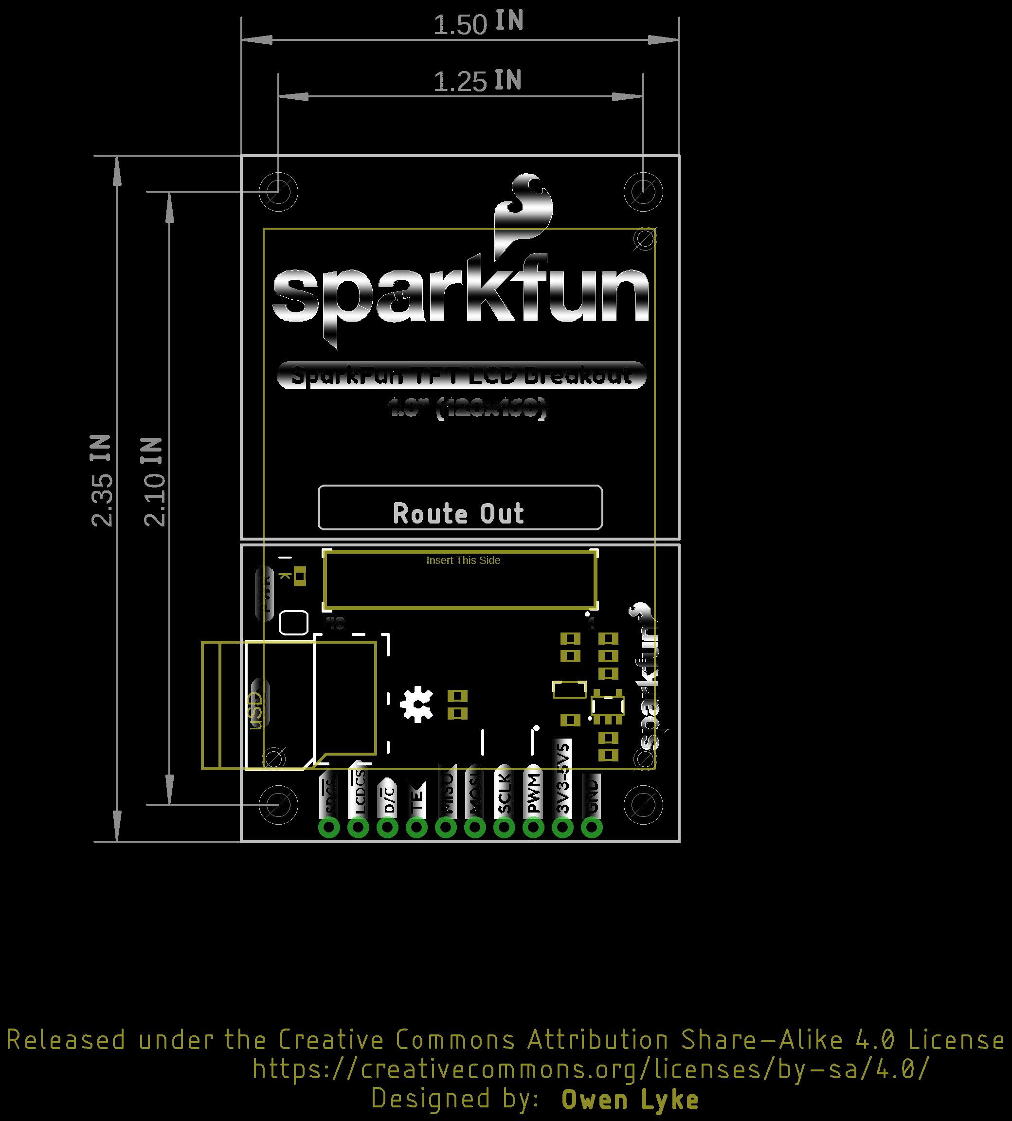
Board Dimensions
The board is 2.35" x 1.50" and includes four mounting holes for 4-40 standoffs by each corner of the board.