Teensy Arduino Shield Adapter Hookup Guide
 Toni_K
Hardware Assembly
So you've got a bag of parts and are ready to get your Teensy interfaced with your Arduino shields. It's time to bust out that soldering iron!
We're going to solder the adapter together in order of smallest profile to largest. This will help make it easier to reach all the soldering points with the iron, as well as make it easier to line all the items up properly.
Battery Holder
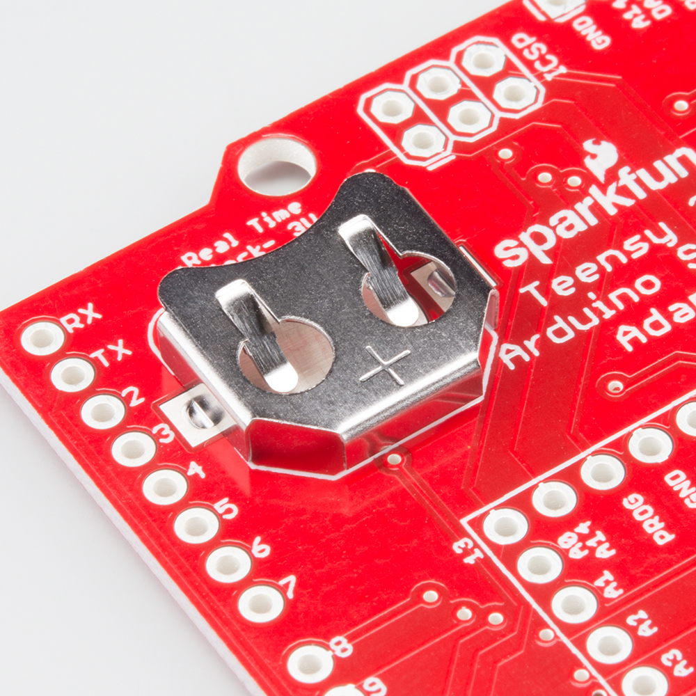
First, insert the battery holder and ensure it is sitting flush on the board. Flip the adapter over, and solder the connectors. Keep in mind that the battery clip is all metal and will conduct heat, so don't burn yourself!
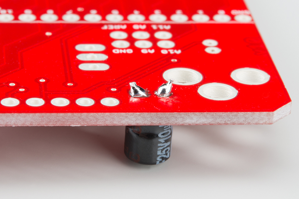
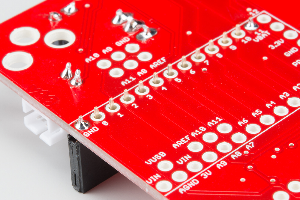
Because the battery clip will endure a lot of strain on battery insertion or removal, you want to make sure you fully connect the pins to the board. Make sure your solder points look nice and filled in, like this:

Capacitor
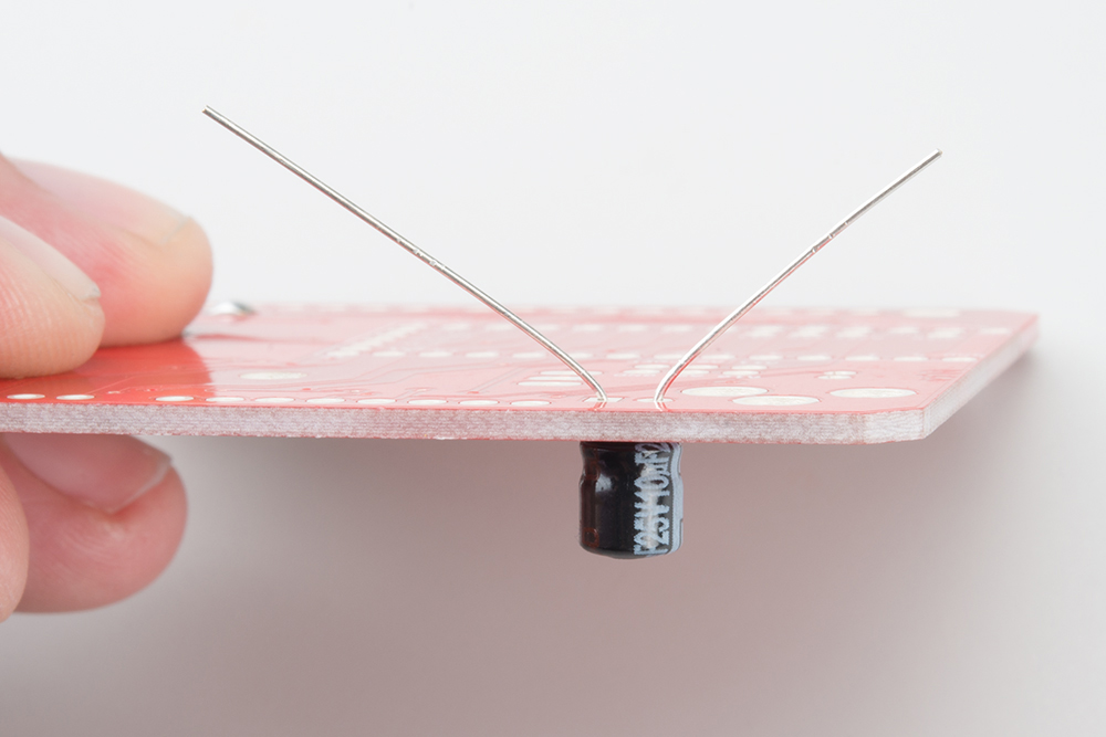
The next component to solder is the capacitor. The cap is polarized, so make sure you insert it correctly into the board. The negative side of the cap should be inserted closest to the barrel jack footprint.
Once you insert the cap, bend the legs out a bit to hold the capacitor flush against the board while you solder it.
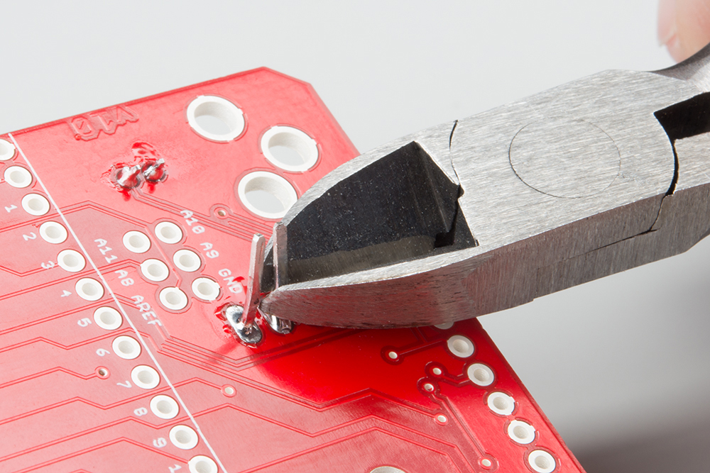
Once you've soldered the capacitor legs, clip any excess leg.
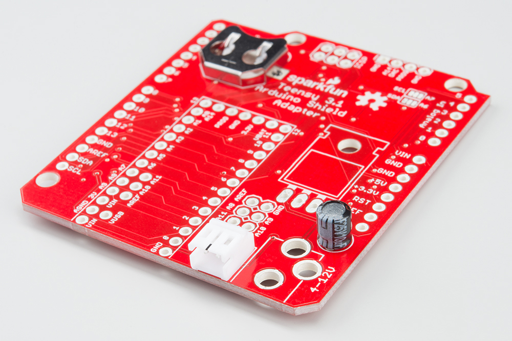
JST Connector
Next, insert the JST connector. This part tends to need a bit of a push to insert fully into the board, so make sure you get it sitting flush before soldering. Make sure the opening on the connector sits along the board edge and isn't inserted backwards.
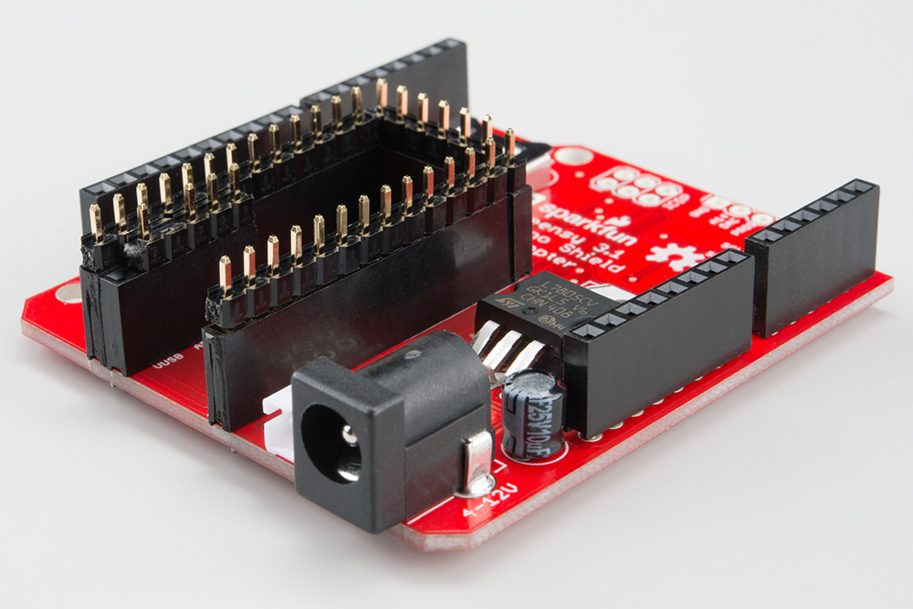
Voltage Regulator
The voltage regulator does tend to be a bear to insert properly, so take your time with this step. First insert the regulator legs into the board. Make sure the regulator is inserted in the correct orientation, with the metal tab towards the ICSP header on the board and the plastic body casing closest to the JST connector.

Once you've verified the regulator is oriented correctly, but before soldering, bend the regulator down towards the PCB. The mounting hole on the regulator should match up with the mounting hole on the PCB.
Solder the regulator legs and clip any excess. This part does regulate the project voltage, so make sure to get a good solder connection on all the pins and ensure there are no jumpers or clippings that could short the board.
Female Headers for Teensy
At this point, you will need to determine how you want your adapter shield to interface with your Teensy and your Arduino shields. The steps shown are our recommended method of interfacing everything, but you can customize this. Please check our tutorial on Getting Started with the Teensy to see other possible configurations.
Take the female headers from your kit, and cut them down into individual strips to fit in the Teensy footprint. Plug in the headers, and verify that they line up well. You may also need to use one of the 6-pin female headers on the short edge of the Teensy footprint.
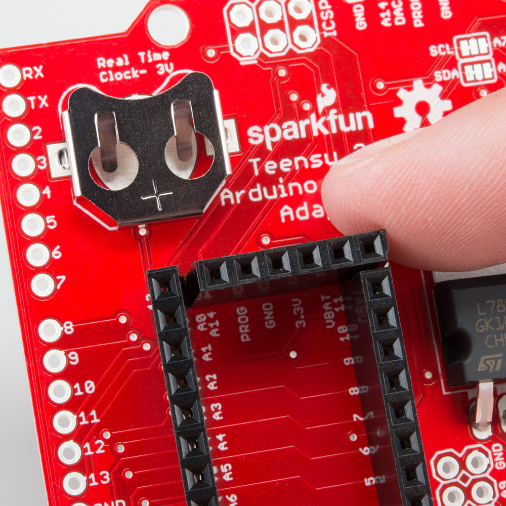
If you have gaps between the headers like shown above, you may need to file down the edges of the connectors to get everything to fit compactly. Start soldering the header rows one at a time. To help keep them straight as you solder, we recommend tacking the first and last solder points first.
This allows you to easily fix any poorly inserted or angled headers that may occur.

If you have decided to solder all of the Teensy pins, you will also need to solder in the inner row of headers on the shield.
Shield Headers
Next, solder on the 10-pin, 8-pin, and 6-pin headers onto the Adapter board. To make sure you line these headers up properly, we recommend using a pre-soldered shield as a soldering jig to hold the adapter headers in place.
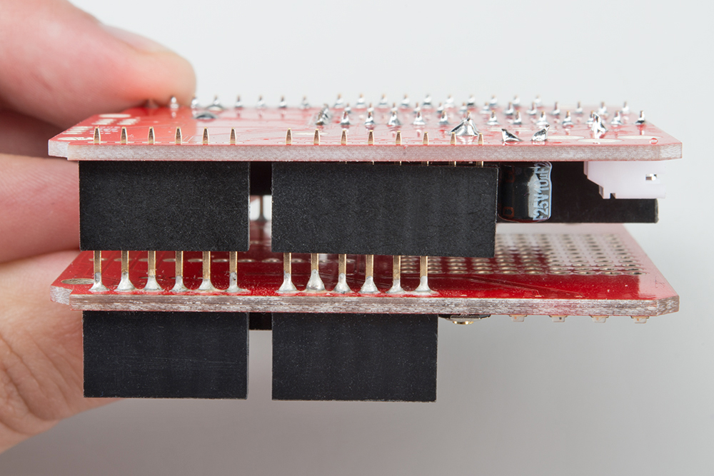
Keep in mind that you may need to add on the stackable headers from your kit onto your board in order to provide enough clearance between the Teensy and the shield you use.
Barrel Jack
The final part to solder is the barrel jack. Notice that when you insert it, the through holes are much larger than the standard headers.
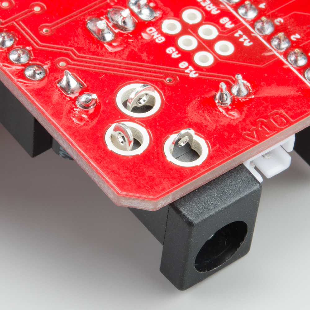
Because of the large plated through holes, you will need more solder and heat to properly connect these and fill them in (just like on that battery clip!). Be patient, and take it slow, to ensure you don't burn the PCB or any traces.
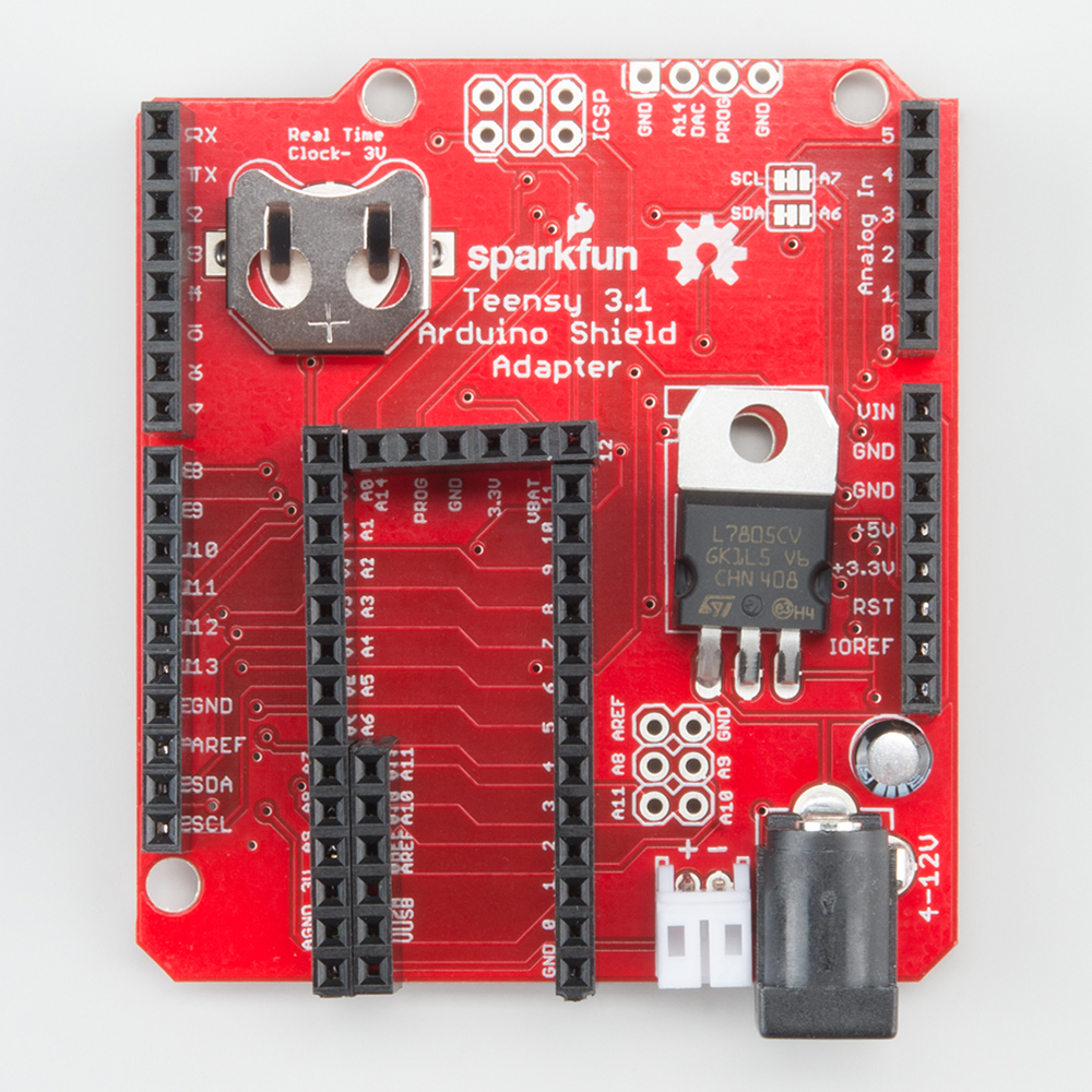
That's it! Your adapter should now be soldered and ready to go.
Teensy Headers
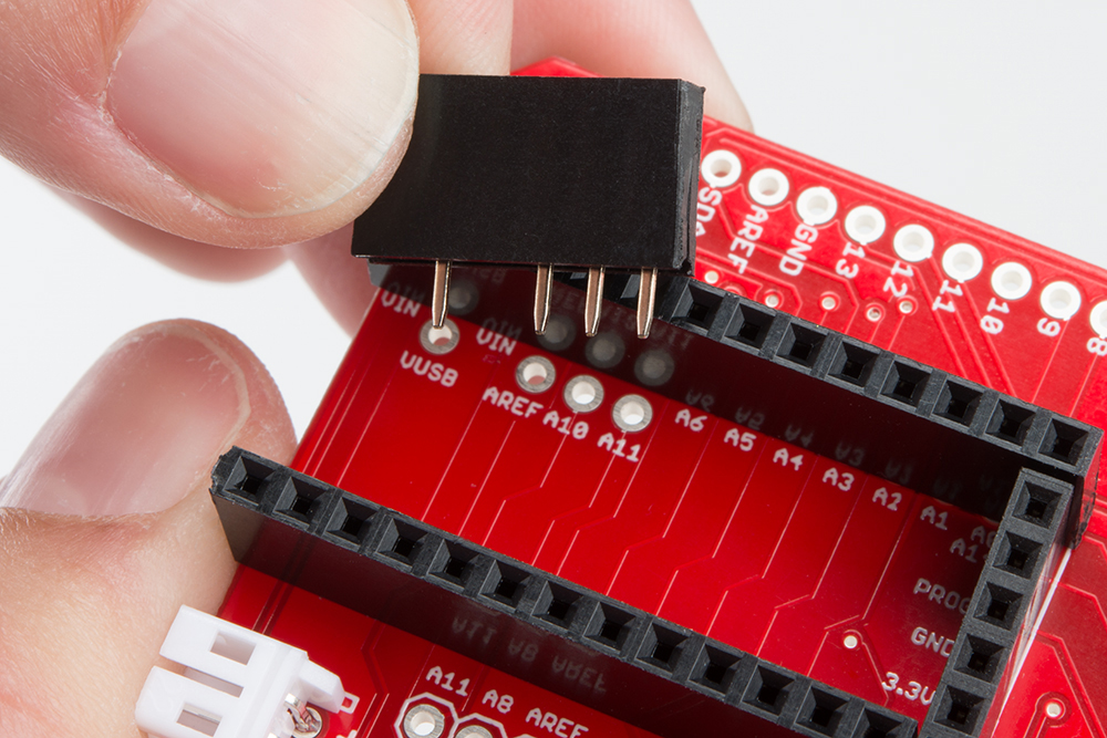
Now that your adapter is completed, you can use this as a soldering jig to connect the male headers to your Teensy. Break the strip into smaller parts, and insert them into the pre-soldered headers on the adapter. Plug the Teensy on top, and solder away!
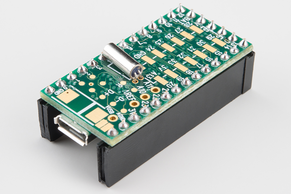
Crystal
If you intend to use the RTC on the Teensy 3.1 or Teensy 3.2, you will need to solder the crystal onto the Teensy. You can solder it via the bottom or the top, but keep in mind you should insert it where it is least likely to get knocked or short the body of the crystal onto other components.
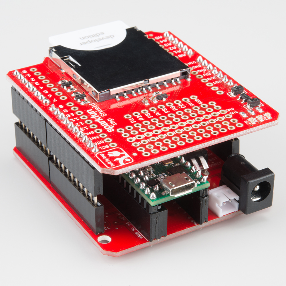
Plug it all in
Once everything is soldered properly, it's time to put your boards together. If you did not solder the Teensy directly to the adapter, plug the Teensy into the adapter, and insert whichever shield you've chosen to connect.
Plug in your Teensy via USB, upload your code, and you're good to go!
Don't forget to plug in your coin-cell battery, if you intend to use the RTC. This does not work with the Teensy LC.