SSOP-16 to DIP Adapter Hookup Guide
 Byron J.
Assembly
Assembling the adapter is fairly straightforward, but there are a couple of tricks that make it easier.
Materials
To build up an adapter, you'll need the following pieces.
- An SSOP-16 integrated circuit to adapt.
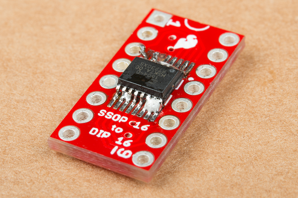
- The 16-pin SSOP to DIP adapter board.
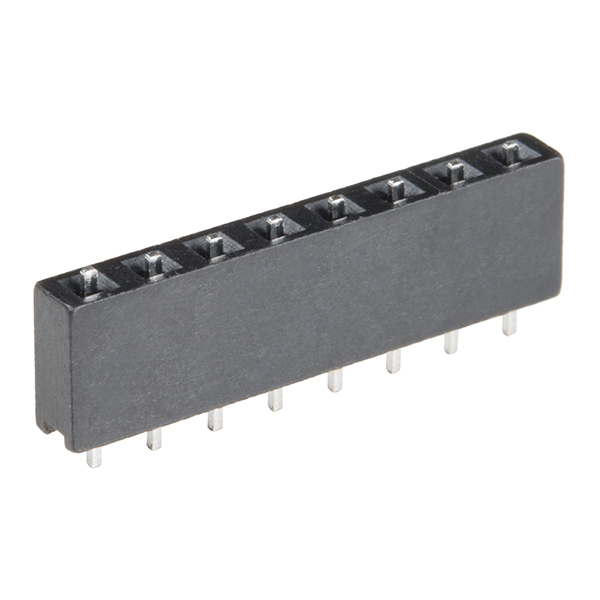
- Some break away male headers or flip pins.
- Some solder, either leaded or lead-free.
- Solder flux, either liquid, or in a pen-type applicator.
- Solder wick, to help clean up excess solder.
Tools
The following tools are also recommended.
- A soldering iron with a fine-point tip.
- A magnifying glass or loupe.
- Cross-lock tweezers.
- A solderless breadboard, to use as an assembly jig.
Building An Adapter
Snap Boards Apart
The array of boards was scored when it was manufactured. If you bend along the scores, the boards snap apart easily.

Prepare To Solder
It's easiest to solder the IC in place before you mount the headers, so you don't have to work around the protruding pins.
If this is your first time soldering surface mount ICs, patience and a steady hand are the key to good solder joints.
- Neatness Counts -- you want to put on enough solder to join the legs to the pads, but not so much that adjacent legs are accidentally bridged.
- Work Quickly -- if you leave the hot soldering iron on the board too long, you risk burning the traces and pads off the board. You want the iron at a temperature where the solder flows almost immediately when you apply it to the iron. Somewhat counter-intuitively, a hotter iron can be less damaging than a cooler one -- having the iron at a hotter temperature allows you to work more quickly, reducing the potential for damage.
Solder IC In Place
To install the IC, we'll be using a technique known as "drag soldering." In drag soldering, we drag a blob of solder across the IC pins, depositing some on each as it goes by. If there's too much solder after dragging, we'll remove it with wick.
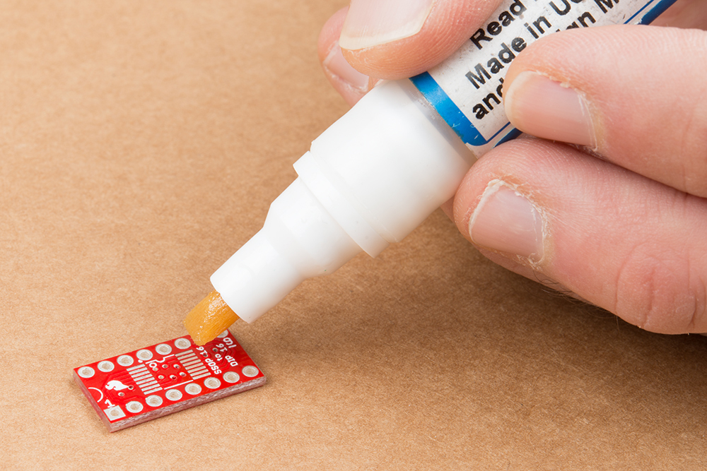
First, apply flux to the PCB. Flux cleans off the thin layer of oxidation the forms on the pads and allows molten solder to flow onto them.
Pin 1 of the IC is usually marked with a small dimple or notch in the IC body. Line these marks up with the corresponding marks in the PCB silkscreen. The silkscreen actually has three marks: a notch at one end of the IC, a dot within the IC outline, and a dot just outside the IC (which remains visible once the IC is soldered down).
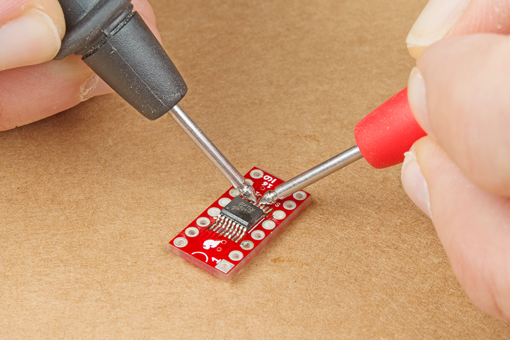
To get started, flow a tiny bit of solder onto pads on opposite corners of the SSOP footprint.
Grab the IC with the tweezers, and orient it over the footprint. Reheat one of the solder blobs from the previous step so the IC lead adheres to it. The solder should flow onto the IC legs, tacking the part in place. Press the IC down flat before the solder cools.
Then repeat this on the opposite leg, to hold the IC in place for the rest of the soldering operation.
When it's in place, doublecheck that the rest of the pins are reasonably aligned with their pads. If the placement needs adjustment, reheat one corner, and move the IC.
If you're careful and have a dainty soldering iron, you can proceed around the chip, soldering down each lead individually.
Of course, we're not especially dainty. The tip of our iron is gigantic compared to the lead pitch of an SSOP, so we're going to use a different technique, known as drag soldering.
To start drag soldering, heat a pin with the iron, then flow a blob of solder onto it. Once the solder flows, use the iron to drag the blob across the remaining leads.
As you drag the blob, it will adhere each pin to the corresponding pad.
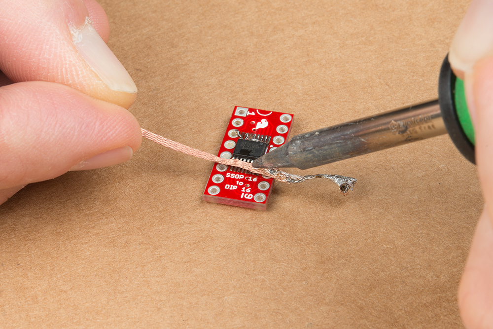
When you reach the end of the line of pins, there might be some blob remaining, and there will probably be some excess solder bridging adjacent pins.
Use the solder wick to clean these up.
Repeat the process down the other side of the IC.
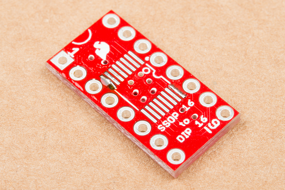
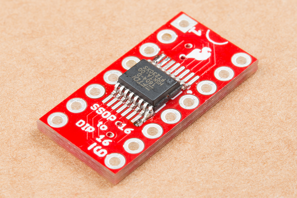
When you're done, take a moment to inspect your work. Check that each lead has a solder fillet to the pad underneath and that leads aren't shorted to their neighbors. It gets harder to touch things up once the pins have been soldered on.
Solder In Header Pins
With the IC in place, now you can solder on the pins. We'll demonstrate using both plain break-sway headers and flip pins. Flip-pins are special pins that are the size and shape of regular DIP-IC legs. They fit in breadboards and IC sockets better than plain square-pin headers.
Regular Headers
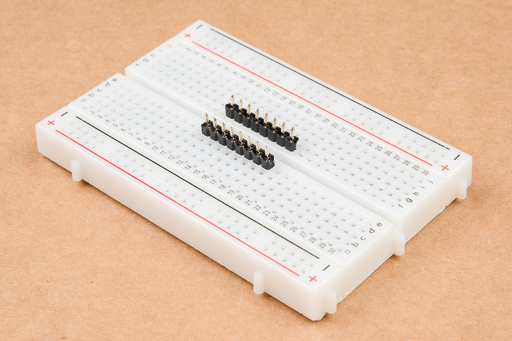
Soldering in regular headers is easier if you have a jig that can hold the pins while you solder. It turns out that a solderless breadboard has a bunch of holes with the proper alignment!
Start by breaking 8-pin segments off the header. Insert them into the breadboard, two rows apart.
Set the PCB over the headers. Take care to keep the pins aligned straight up and down.
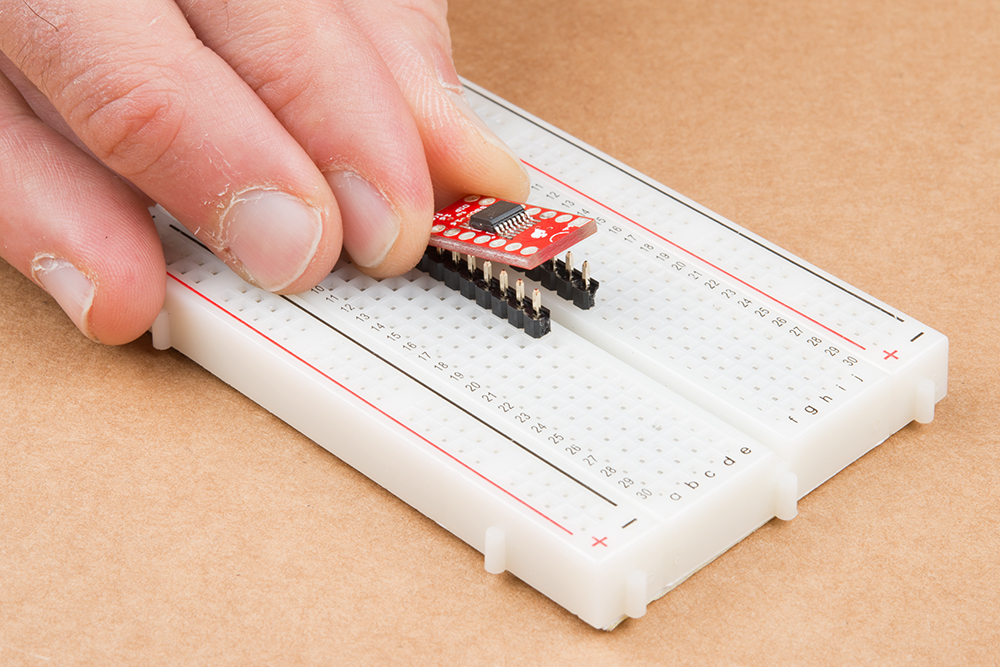
Work your way around the PCB, soldering each pin from the top of the board.
Flip Pins
Flip pins come packaged in a black plastic shroud, which keeps them aligned until they have been installed. The shroud also works as an assembly jig.
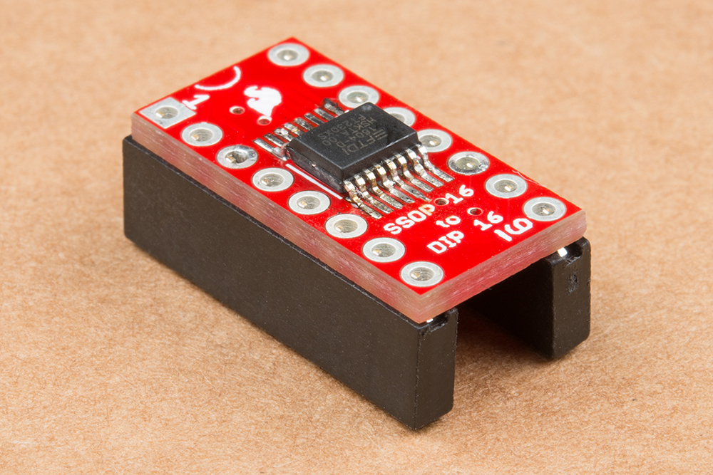
To start, stand two sets of flip pins up on your workbench. Then place the PCB on top of the pins. The tail on flip pins is as long as the PCB is thick -- they won't protrude above the PCB.
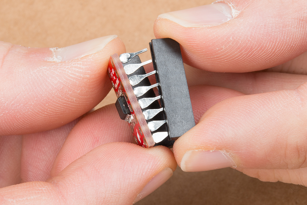
Work your way around the board, soldering in each pin. Take care to keep the pins aligned perpendicular to the plane of the bench top. Once the pins have been soldered on, carefully slide the plastic pin aligner off, revealing the IC-type pins.
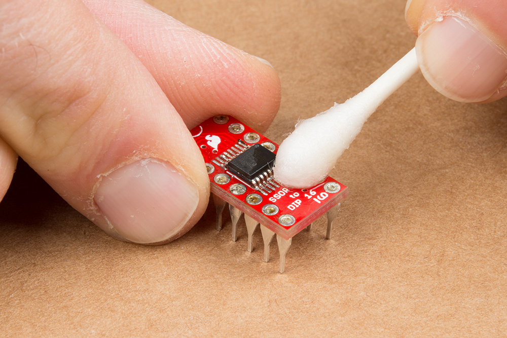
Deflux
Once you've finished soldering, look at the solder joints. If they appear to have a yellow or brown coating on or around them, the board has flux residue (under a magnifying glass, it might look like amber or burnt sugar). Flux is acidic and can cause problems with long-term reliability, so it's best to clean it off.
You'll have to check the documentation for your solder for the proper cleaning methodology. Some flux is water soluble, while some requires a solvent like isopropyl alcohol or acetone.
Verify
Before we jump into applications of the SSOP-to-DIP adapter board, let's take a moment to doublecheck our work.
A quick visual inspection can help spot solder bridges or solder joints that didn't flow properly. It's also a good time for one last check, to make certain that pin one of the SSOP is properly oriented.
For a little extra confidence, you can also use a multimeter in continuity mode to verify that the legs of the SSOP are connected to the pads but not bridged to their neighbors.