SSOP-16 to DIP Adapter Hookup Guide
Using The Adapter
Adapter Orientation
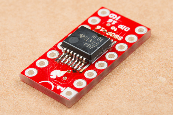
The pins of the DIP footprint are rotated 90° in relation to the pins of the SSOP. We covered the pin-1 markings for the SSOP in the assembly section.
Pin 1 of the DIP footprint is marked two ways. The solder pad for pin 1 is square, while the others are round. It also has a small 1 in the silkscreen near the pad.
Pins 1 and 9 are also marked in the legend silkscreened on the bottom of the board.
Case Studies
On a Breadboard
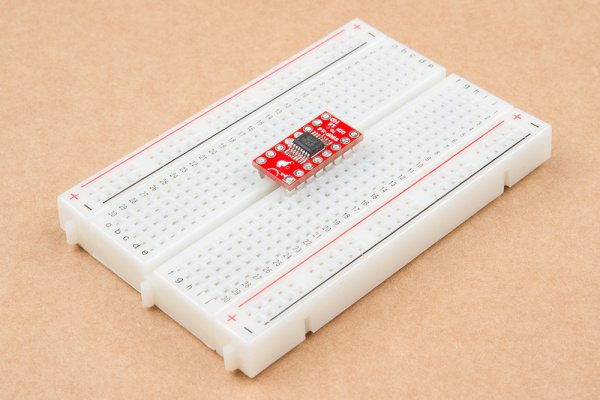
This adapter is useful when you want to build a breadboard prototype using a chip that's only available in SSOP. It allows the chip to properly fit the rows of the breadboard.
Upgrading Old Devices
Another common use of a SSOP-to-DIP adapter is upgrading or modifying existing equipment...or, as in this case, saving your bacon when you've purchased components with the wrong footprint.
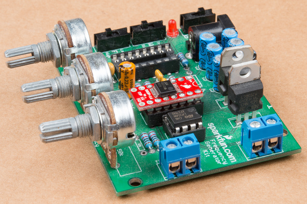
We're working on restoring an old SparkFun Function Generator Kit and needed a 74HC04 logic chip. When we ordered it, we didn't read the description carefully enough, and we got a 14-pin SSOP IC. Unfortunately, it needed to fit it into a DIP footprint on the board. Thankfully, we've got an adapter board to help.
If you look closely, you'll notice two things in the above photo: first, the IC only has 14 pins on a 16-pin adapter board. Second, it is a wider SSOP package than we've seen in the other examples. Thankfully, the land pattern on the PCB has extra-long pads to accommodate it.
Since the PCB already had a socket, we opted to use flip pins on the adapter. We're fitting a 14-pin chip on a 16-pin adapter, so we opted to keep pin-1 aligned on both pieces. This also means that the chip is two pins short -- we're not using pins 8 and 9 on the adapter, and pins 10 through 16 on the adapter are off by two, connected to IC pins 8 to 14.


