SparkFun USB UART Breakout (CY7C65213) Hookup Guide
 SFUptownMaker
 Introduction
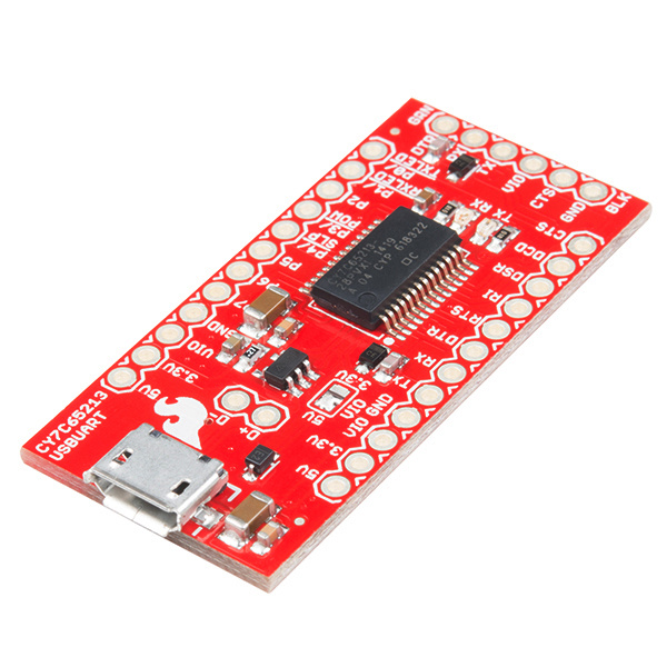
The CY7C65213 USB to UART serial breakout is designed to provide users with a means to access all available I/O pins on the CY7C65213 part and to provide a 6-pin UART header that is compatible with other SparkFun breakout boards. This tutorial will explain the use of the board in greater detail.
We will explain the layout of the board, proper usage of the jumpers on the board to change the I/O voltage, and use of the Cypress configuration application to change default settings on the board to meet your own needs.
As we work through the Hookup Guide, you may find it useful to have the CY7C65213 USB to UART Datasheet on hand.
Suggested Reading
At a minimum, you should be familiar with asynchronous serial communication, as that is the central function of this chip. You should also have some idea of what we mean when we talk about different logic levels, or voltages, so you know when to change the logic level for your board.
Hardware Overview
Here we will go over the various parts of the board, providing an explanation for each and detailed usage instructions.
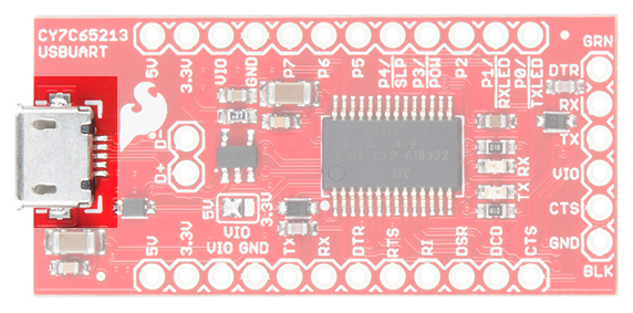
- Micro-B USB port---This is where the cable from the host device connects to this PC. Power can be supplied through this connector to this board, as well as to the circuit it is attached to.
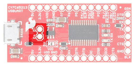
- USB signal lines---These two pads break out the D+ and D- signal lines for user access. These signals can then be brought out to a different connector if desired.
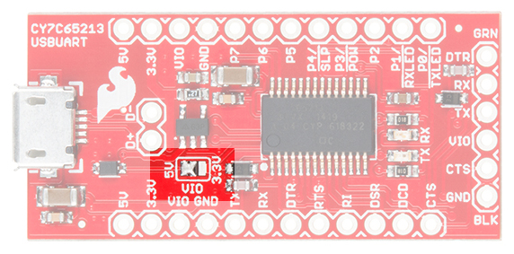
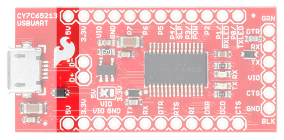
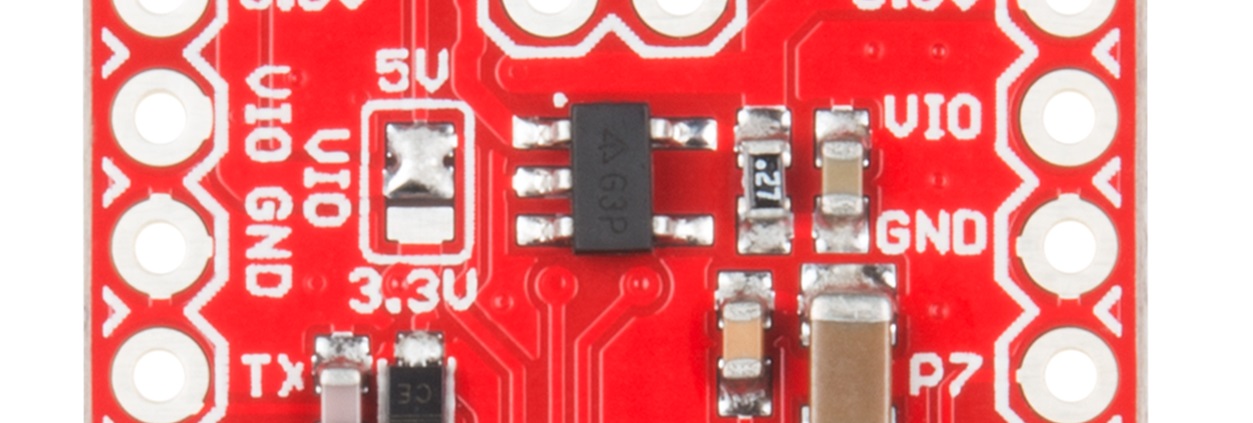
- VIO selection jumper---This jumper is used to select the voltage that appears at the VIO pin on the 6-pin serial header. The left two pads can be closed to supply 5V directly from the USB power line, or the right two pads can be closed to supply 3.3V via an onboard 500mA regulator. If the attached board is going to provide a voltage reference for an alternative voltage (say, 2.5V or 1.8V), remove all solder from this jumper.
- ** 5V pin**---Supplies 5V directly from the USB power.
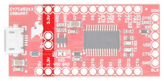
- 3.3V pin---Supplies 3.3V from a 500mA 3.3V regulator connected to the USB power line.
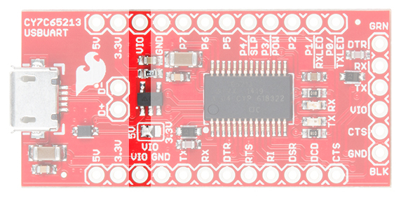
- VIO pin---Tied to the VIO pin on the 6-pin serial header, this will either be connected to 5V or 3.3V, depending on the VIO selection jumper, or it will reflect the voltage present on VIO if the downstream board is providing a reference voltage for this board.
- ** Variable purpose I/O pins**---The purpose of these pins will be discussed later, but in normal operation they are seldom, if ever, used.

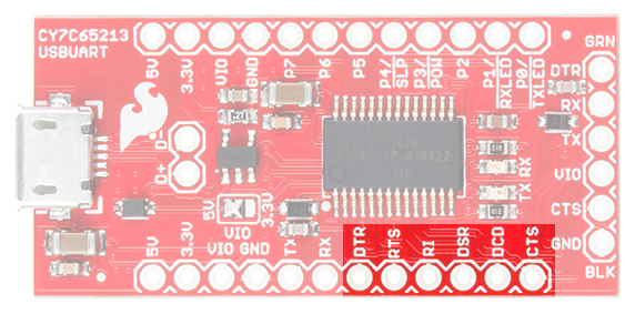
- DTE port pins---These pins provide the same functionality as the similarly named pins on an RS-232 port, albeit at VIO voltage rather than the bipolar voltage of true RS-232. DTR and CTS are the most commonly used. We'll discuss the role of these pins later.
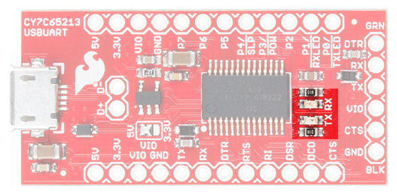
- TX and RX LEDs---These LEDs light up when data is being transferred over the serial channel. The TX LED lights up when data is being sent from the host to the attached board, and the RX LED lights up when data is being sent back from the attached board to the host.
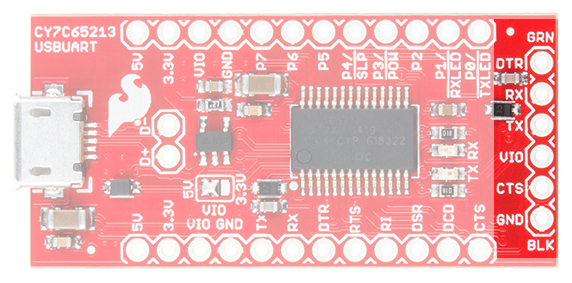
- 6-pin serial header---A longtime standard on SparkFun (and other) boards, this header contains the minimum necessary signals for communicating with a downstream board. It can be used to program Arduino Pro and Pro Mini boards, among others.
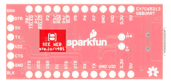
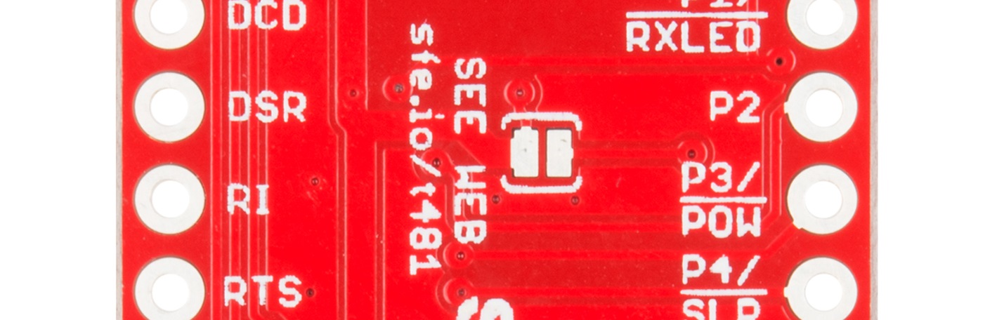
- Low-voltage select jumper---On the underside of the board, you'll find a jumper that should only be set in cases where VIO is 2V or less. Since there is no onboard reference for that voltage, this will be in cases where the downstream board is providing the reference voltage.
Installing Drivers
Windows
For Windows OS, you will need to install drivers for the chip if this is the first time connecting the CY7C65213 to your computer. Head over to Cypress to obtain the driver files:
Max OS X and Linux
For those using Mac OS X or Linux, there are no installation steps necessary.
Programming an Arduino Pro or Pro Mini
The CY7C65213 chip can be used to program an Arduino Pro or Pro Mini, just like SparkFun's other FTDI-based USB to UART chips. As a basic example for getting started with this board, we will be demonstrating this hardware connection.
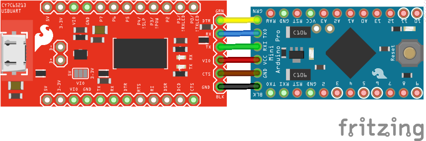
Note that, unlike the other boards, you'll need to buy some kind of header to interface to the Arduino board, as no header comes pre-soldered to the CY7C65213 breakout. This affords you the option to choose the connector that best suits your purpose or to solder wires directly between the two boards.
Once the board is connected and the driver is installed (which should happen automatically on all major operating systems), no other changes are needed for the board to be used as a programming connection. Simply select the COM or TTY port in the Arduino software and proceed as normal.
Using the Board at Voltages Below 2V
Hardware Changes on the PCB
To enable support for voltages below 2V, you must first disconnect the board from your PC and adjust the jumpers on the PCB.
Shown below is the VIO selection jumper. You must remove all solder from this jumper before proceeding. We suggest using some solder wick to achieve this.
Now, you must close the low-voltage jumper on the bottom side of the PCB with solder.
We've created a special footprint just for solder jumpers to make it as easy as possible to close the jumper. Simply heat both pads and then apply the solder to the pads; a bridge should form naturally. Do not apply too much solder.
Software Settings on the PC
Cypress offer a downloadable configuration utility for this chip. Sadly, it is currently offered only for the Microsoft Windows platform. You'll need to download and install this utility before you can use the chip for voltages below 2V.
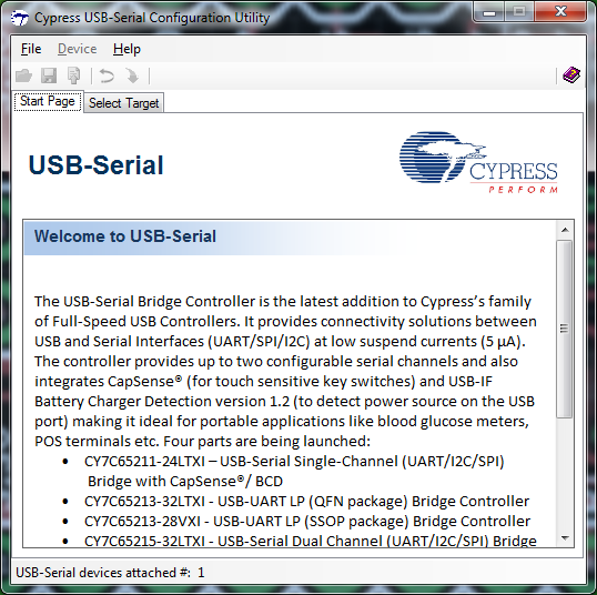
When you first open the utility, this is what you will see. In the lower left, you should see the utility displaying the number of Cypress USB UART boards only (other manufacturers' chips, such as FTDI, Arduino or Prolific will not be reflected in this number). Assuming your chip has shown up here, go ahead and click on the Select Target tab at the top.
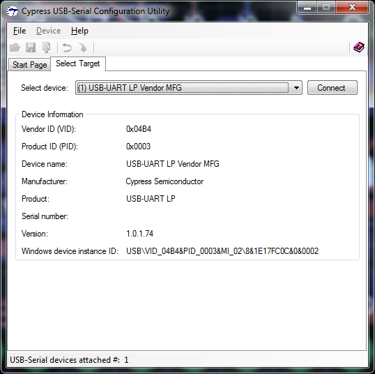
This is the Select Target tab. The dropdown will list available Cypress USB UART boards, and information (probably more than you want or need) will appear in the window below it. Click the Connect button to proceed, making sure that there are no open terminal windows (such as the Arduino IDE serial port monitor) using this board at the moment first.
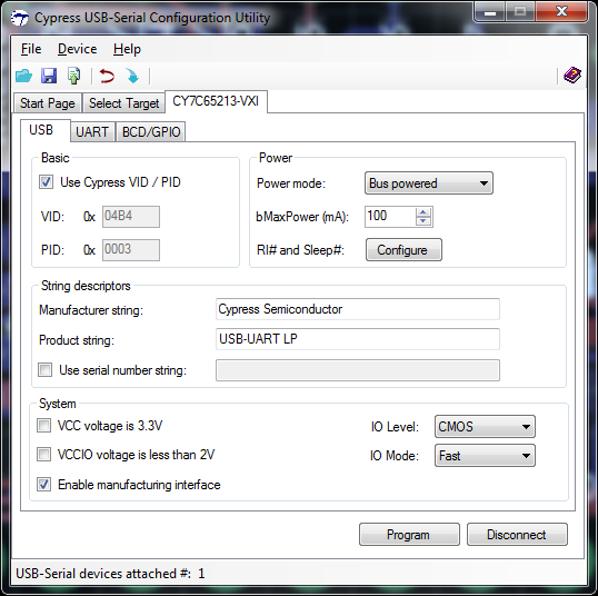
A new tab will appear and become automatically selected. In the lower left corner of this new tab, you can see a checkbox labeled VCCIO voltage is less than 2V. Click this checkbox, then click the Program button at the bottom of the page. The chip is now configured for use at less than 2V.
Resources and Going Further
For more on the Cypress CY7C65213 USB UART chip, please check out the links below:
- USB UART SDK from Cypress --- If you are an experienced system-level software developer, it's possible to use the Cypress drivers to achieve additional goals with the 7C65213 chip. It has onboard I/O, for instance, which can be used for out-of-band communications with the target PCB.
- CY7C65213 USB UART Breakout Schematic (PDF)
- CY7C65213 USB UART Breakout Eagle Files (ZIP)
- CY7C65213 USB UART Datasheet (PDF)
- SparkFun CY7C65213 USB UART Breakout GitHub Repository (hardware source files)
Check out these related tutorials for some inspiration for your next project: