SparkFun RFID Starter Kit Hookup Guide
 a_cavis
 Introduction
The SparkFun RFID Starter Kit gives you the tools you need to start reading RFID tags with your computer or microcontroller!
Required Materials
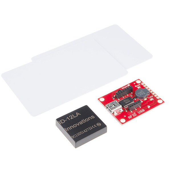
The kit contains:
You will also need a USB mini-B cable to connect the USB reader to a computer.
Recommended Reading and Viewing
The ID-12LA module has a serial output. If you've never worked with a serial device or a terminal program before, you might want to take a look at these tutorials first.
- Serial Communication
- Serial Terminal Basics
- RFID Basics
- Tim's RFID Comparison video - Let Tim from Tech Support walk you through our entire line of Low Frequency RFID options, complete with range tests.
- SparkFun Simple Sketches - RFID Starter Kit video - A simple video demo of the RFID Starter Kit in action.
Hardware Overview: RFID USB Reader
The RFID USB Reader has the following features:
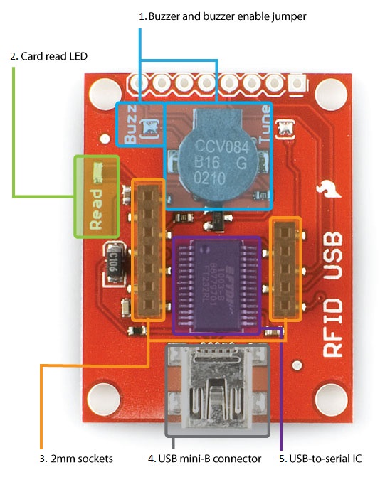
Buzzer and Buzzer Enabled Jumper - A buzzer that sounds when a card is read. If you are using the RFID kit in a stealth application, you can disconnect the buzzer by removing the blob of solder on the Buzz jumper.
Card Read LED - A "card read" status LED.
2mm RFID Sockets - 2mm-spaced sockets that fit three of SparkFun's RFID modules (the ID-3LA, the ID-12LA, and the ID-20LA).
USB mini-B Connector - A USB mini-B connector to connect to a computer's USB port.
USB-to-Serial IC - An FTDI232RL USB-to-serial IC that converts the module's TTL serial output to USB.
Hardware Hookup
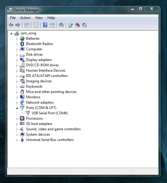
Place the ID-12 module onto the RFID USB Reader, and plug the base into your computer with a USB mini-B cable. Depending on your operating system, you may need to install FTDI drivers after plugging in the base station.
Open a terminal program of your choice. If you've never used a terminal program before, here's a guide to choosing and using them.
First, use the Arduino IDE's built-in serial monitor:
- Open the Arduino IDE.
- Go to Tools > Port and select the RFID reader's port.
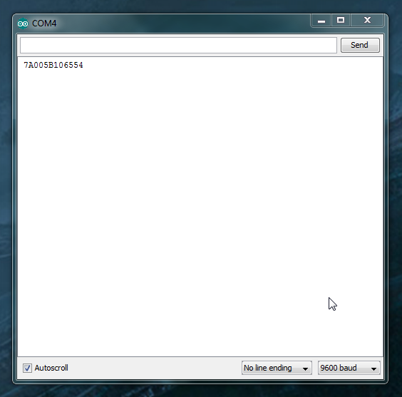
- Go to Tools > Serial Monitor. The default terminal settings (9600 baud, no line ending) are fine. The monitor should be blank.
Wave a card over the reader. You should hear a beep and see something like this.
Now, we'll do the same thing in RealTerm. (Mac users, you can try this section using CoolTerm)
RealTerm may look like the cockpit of a 747 compared to the Arduino serial monitor, but it has several helpful features. Keep the RealTerm tutorial open if you need it.
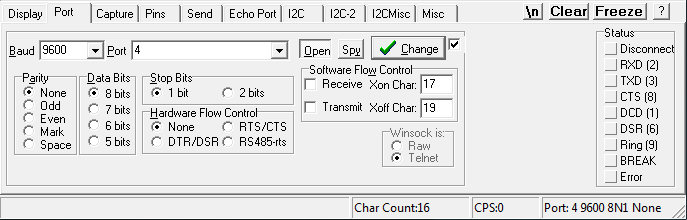
4 and the baud rate to 9600 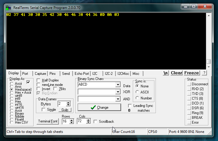
With Display As set to Hex[space], the card data appears as 16 hex bytes instead of 12 ASCII digits like it did in the Arduino Serial Monitor.
Wait, 16 bytes? Where did the extra four come from?
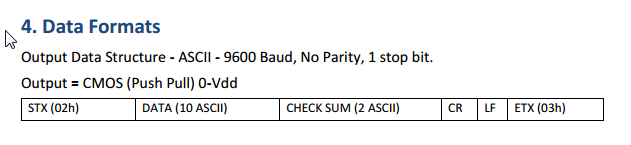
Here's the "Data format" section from the ID-12 module datasheet. The 12 ASCII characters displayed in the Arduino serial monitor are just the filling in a 16-byte sandwich, with four more non-printing characters (STX or start-of-text, CR/carriage return, LF/linefeed, and ETX/end-of-text) as the bread.
Try switching the Display As setting to ASCII and scan again:
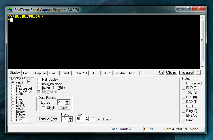
Now the "bread" is visible! That's cool, right?
Example Project
As fun as it is to watch your cards pop up in the serial terminal, you'd probably like to do something with all this power.
The example sketch below scans RFID cards and compares them against trusted cards, then moves a servo to unlock the secured* item of your choice.
* Not suitable for critical applications, e.g. guarding the Hope Diamond.
In addition to your RFID Reader Kit, you will want:
- A microcontroller like the SparkFun RedBoard or the Arduino Uno.
- M/M Jumper Wires
- Breadboard
- A Servo - Larger sizes are suggested for larger locks.
- Break-Away Male Headers to solder to the board's through-holes. (If you need a soldering refresher, take a look at our through-hole soldering tutorial)
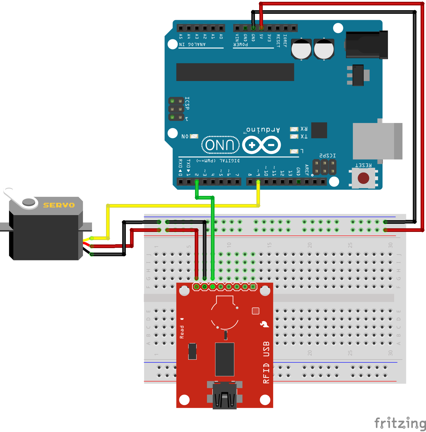
Connect the VCC, GND, and TX pins on the RFID USB Reader to the Arduino's 5V, GND, and D2 pins, and connect the servo to 5V, GND, and D9. Copy the code provided below and adjust values provided in the knownTags[][]{} array that was obtained in the simple hookup so that the Arduino recognizes your RFID tag. Upload the code, open your Serial Monitor by going to Tools > Serial Monitor, and start scanning some cards!
language:c
/*****************************
     RFID-powered lockbox

Written by: acavis, 3/31/2015
Modified: Ho YUN "Bobby" Chan @ SparkFun Electronics Inc., 11/10/2017

Inspired by & partially adapted from
http://bildr.org/2011/02/rfid-arduino/

Description: This sketch will move a servo when
a trusted tag is read with the
ID-12/ID-20 RFID module

----------HARDWARE HOOKUP----------

PINOUT FOR SERVO MOTOR
    Servo Motor ----- Arduino
    GND               GND
    Vcc               5V
    SIG               D9

PINOUT FOR SPARKFUN RFID USB READER
    Arduino ----- RFID module
    5V            VCC
    GND           GND
    D2            TX

PINOUT FOR SPARKFUN RFID BREAKOUT BOARD
    Arduino ----- RFID module
    5V            VCC
    GND           GND
    GND           FORM
    D2            D0

Optional: If using the breakout, you can also
put an LED & 330 ohm resistor between
the RFID module's READ pin and GND for
a "card successfully read" indication.

Note: Make sure to GND the FORM pin to enable the ASCII output format.

--------------------------------------------------

******************************/

#include <SoftwareSerial.h>
#include <Servo.h>

// Choose two pins for SoftwareSerial
SoftwareSerial rSerial(2, 3); // RX, TX

// Make a servo object
Servo lockServo;

// Pick a PWM pin to put the servo on
const int servoPin = 9;

// For SparkFun's tags, we will receive 16 bytes on every
// tag read, but throw four away. The 13th space will always
// be 0, since proper strings in Arduino end with 0

// These constants hold the total tag length (tagLen) and
// the length of the part we want to keep (idLen),
// plus the total number of tags we want to check against (kTags)
const int tagLen = 16;
const int idLen = 13;
const int kTags = 4;

// Put your known tags here!
char knownTags[kTags][idLen] = {
             "111111111111",
             "444444444444",
             "555555555555",
             "7A005B0FF8D6"
};

// Empty array to hold a freshly scanned tag
char newTag[idLen];

void setup() {
  // Starts the hardware and software serial ports
   Serial.begin(9600);
   rSerial.begin(9600);

   // Attaches the servo to the pin
   lockServo.attach(servoPin);

   // Put servo in locked position
   // Note: Value may need to be adjusted
   // depending on servo motor
   lockServo.write(0);

}

void loop() {
  // Counter for the newTag array
  int i = 0;
  // Variable to hold each byte read from the serial buffer
  int readByte;
  // Flag so we know when a tag is over
  boolean tag = false;

  // This makes sure the whole tag is in the serial buffer before
  // reading, the Arduino can read faster than the ID module can deliver!
  if (rSerial.available() == tagLen) {
    tag = true;
  }

  if (tag == true) {
    while (rSerial.available()) {
      // Take each byte out of the serial buffer, one at a time
      readByte = rSerial.read();

      /* This will skip the first byte (2, STX, start of text) and the last three,
      ASCII 13, CR/carriage return, ASCII 10, LF/linefeed, and ASCII 3, ETX/end of
      text, leaving only the unique part of the tag string. It puts the byte into
      the first space in the array, then steps ahead one spot */
      if (readByte != 2 && readByte!= 13 && readByte != 10 && readByte != 3) {
        newTag[i] = readByte;
        i++;
      }

      // If we see ASCII 3, ETX, the tag is over
      if (readByte == 3) {
        tag = false;
      }

    }
  }


  // don't do anything if the newTag array is full of zeroes
  if (strlen(newTag)== 0) {
    return;
  }

  else {
    int total = 0;

    for (int ct=0; ct < kTags; ct++){
        total += checkTag(newTag, knownTags[ct]);
    }

    // If newTag matched any of the tags
    // we checked against, total will be 1
    if (total > 0) {

      // Put the action of your choice here!

      // I'm going to rotate the servo to symbolize unlocking the lockbox

      Serial.println("Success!");
      lockServo.write(180);
    }

    else {
        // This prints out unknown cards so you can add them to your knownTags as needed
        Serial.print("Unknown tag! ");
        Serial.print(newTag);
        Serial.println();
    }
  }

  // Once newTag has been checked, fill it with zeroes
  // to get ready for the next tag read
  for (int c=0; c < idLen; c++) {
    newTag[c] = 0;
  }
}

// This function steps through both newTag and one of the known
// tags. If there is a mismatch anywhere in the tag, it will return 0,
// but if every character in the tag is the same, it returns 1
int checkTag(char nTag[], char oTag[]) {
    for (int i = 0; i < idLen; i++) {
      if (nTag[i] != oTag[i]) {
        return 0;
      }
    }
  return 1;
}
lockServo.write(0) to a higher value like lockServo.write(10).Using the RFID Reader Breakout
For Arduino projects, you can also use the SparkFun RFID Reader Breakout which gives the module a place to sit and breaks out its odd 2mm-pitch pins to a breadboard-friendly 0.1" spacing.
To keep the module removable (and protect it from accidental damage during soldering), you can trim 2x 2mm XBee Sockets to size using a diagonal cutter and solder them to the top of the breakout. You will need to sacrifice a header pin when cutting the 2mm XBee socket and pull/clip a pin from the 1x7 header before soldering to the RFID reader breakout as shown in figure 1. Make sure to test the header on the breakout board with the RFID module before soldering.
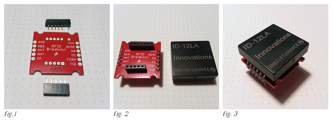
- Fig. 1 XBee sockets trimmed to size with one pin clipped short.
- Fig. 2 Sockets soldered to the top of the breakout with 0.1" male straight header pins on the bottom.
- Fig. 3 Module and breakout ready for use on a breadboard
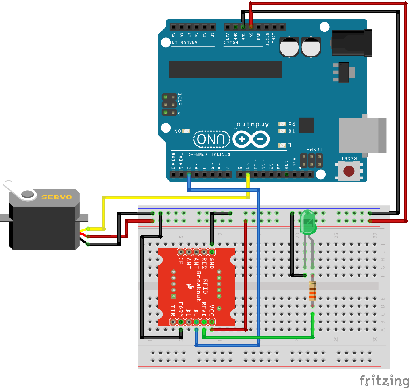
The completed breakout can be used like the larger base station. Here's the same example as above with a green LED and 330 ohm resistor added to the READ pin. TX is labeled D0 on the breakout.
Resources and Going Further
You can use the SparkFun RFID Reader Kit and an Arduino to control access to just about anything!
Instead of moving a servo, how about controlling a relay like the PowerSwitch Tail II. No intruder will ever use your soldering iron, toaster, or electric blanket without permission again!
Rob's NCWP (Non-Crappy Wedding Present) Tutorial -- An RFID reader (plus the rest of Rob's parts list) could be all that's separating you from true love.
For more RFID inspiration, check out these additional resources:
Simultaneous RFID Tag Reader Hookup Guide
RFID Basics
SparkFun Qwiic RFID-IDXXLA Hookup Guide
Qwiic Dynamic NFC/RFID Tag Hookup Guide

Interested in more RFID?
We've got a page just for you! Get an overview of the basics of how RFID works, the hardware needed and tutorials to get you started.