SparkFun Qwiic Thermocouple Hookup Guide
Hardware Overview
MCP9600
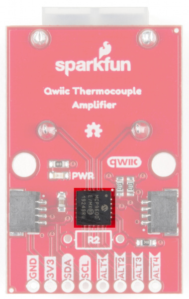
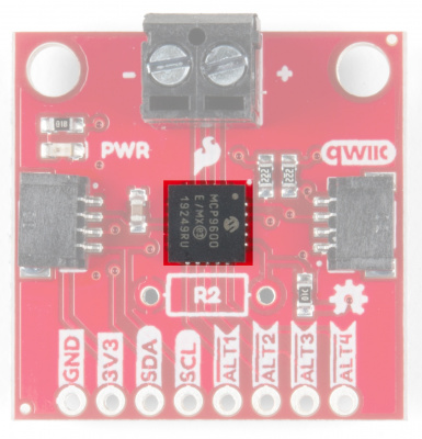
At the heart of this board is the MicroChip Technology Inc MCP9600 Thermocouple EMF to Temperature Converter. Inside this chip are two temperature sensors, one for the thermocouple itself (the hot junction) and one for the chip itself (the cold junction). In addition, the MCP9600 has four onboard temperature alerts that allow you to set a temperature limit to trigger an interrupt when the temperature reaches a certain value. This frees up your microcontroller and your I2C bus. The MCP9600 can also be put into alternate operation modes in order to save power. The sensor supports a burst mode, where it will take a specifiable number of samples, return the results, and then go to sleep. More information can be found in the MCP9600 Datasheet (PDF).
 |
 |
|---|---|
| PCC Connector | Screw Terminal |
Power
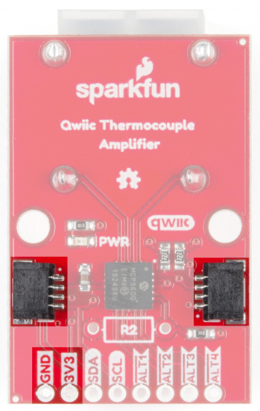
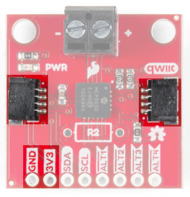
Ideally, power will be supplied via the Qwiic connectors on either side of the board. Alternatively, power can be supplied through the header along the bottom side of the board labeled 3V3 and GND. The input voltage range should be between 2.7-5.5V.
 |
 |
|---|---|
| PCC Connector | Screw Terminal |
Qwiic Connectors
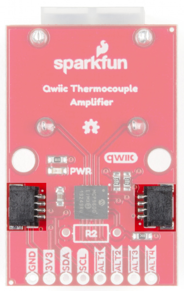
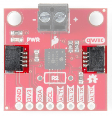
There are two Qwiic connectors on either end of the SparkFun Qwiic Thermocouple boards to provide power and I2C connectivity simultaneously. The I2C address of the board is 0x60 by default , but has 7 other addresses the board can be configured to use.
 |
 |
|---|---|
| PCC Connector | Screw Terminal |
I2C Pins
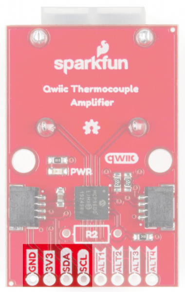
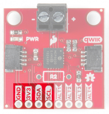
The I2C pins break out the functionality of the Qwiic connectors. Depending on your application, you can connect to these pins via the plated through holes for SDA and SCL.
 |
 |
|---|---|
| PCC Connector | Screw Terminal |
Alert Pins
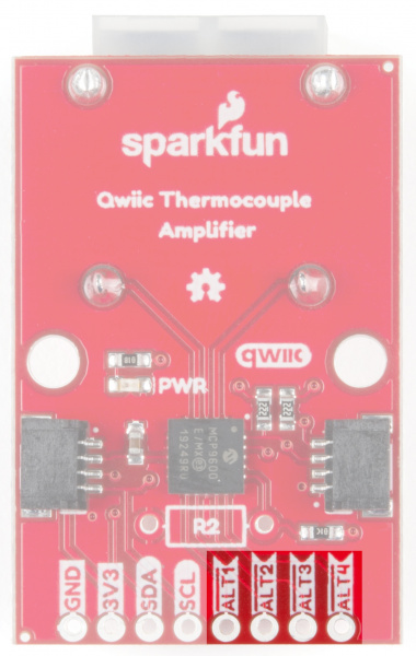
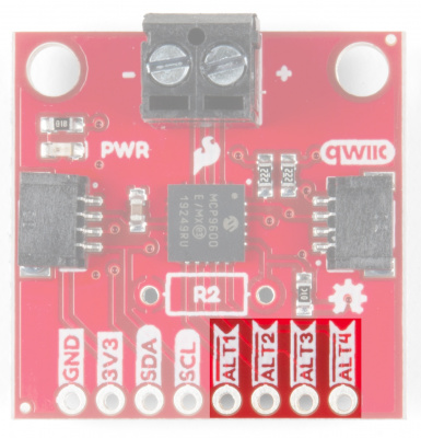
The Qwiic Thermocouple Amplifier has four configurable alert pins. Each alert can be configured for:
- Temperature
- Hysteresis
- Junction Alert - hot (thermocouple) or cold (internal MCP9600 sensor)
- Edge - from cold to hot, or from hot to cold
- Logic Level - active high or active low
- Alert Mode - interrupt or comparator
Check out the Temperature Alerts section of the Arduino library function descriptions to learn more about how to use the alert pins.
 |
 |
|---|---|
| PCC Connector | Screw Terminal |
Jumpers
I2C Jumper
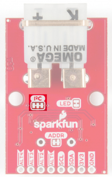
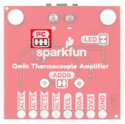
These boards are both equipped with pull-up resistors. If you are daisy-chaining multiple Qwiic devices, you will want to cut this jumper; if multiple sensors are connected to the bus with the pull-up resistors enabled, the parallel equivalent resistance will create too strong of a pull-up for the bus to operate correctly. As a general rule of thumb, disable all but one pair of pull-up resistors if multiple devices are connected to the bus. To disable the pull up resistors, use an X-acto knife to cut the joint between the two jumper pads highlighted below.
 |
 |
|---|---|
| PCC Connector | Screw Terminal |
ADDR Jumper
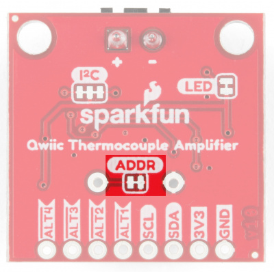
The MCP9600 uses an analog voltage to set the I2C address. By default, the ADDR jumper pulls the address pin low, which gives the board a default address of 0x60. Cutting the jumper pulls the address pin high through a 10K resistor, which will change the address to 0x67.
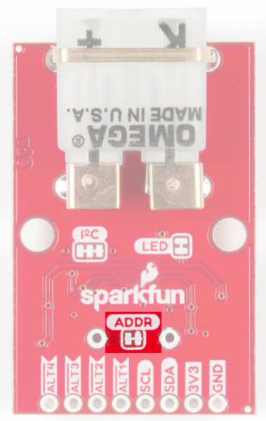 |
 |
|---|---|
| PCC Connector | Screw Terminal |
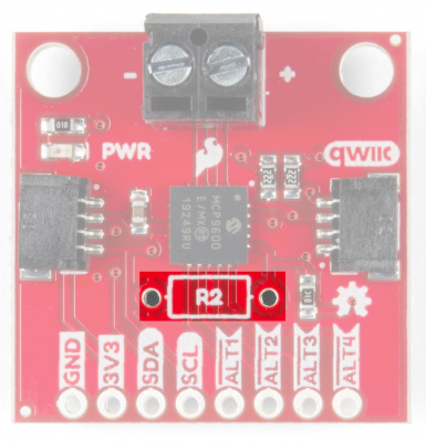
For addresses other than 0x67, a resistor will need to be soldered. Refer to the table below for the resistor value and corresponding address.
| Address | Resistor (kΩ) |
|---|---|
| 0x60 | 0 |
| 0x61 | 2.2 |
| 0x62 | 4.3 |
| 0x63 | 7.5 |
| 0x64 | 13 |
| 0x65 | 22 |
| 0x66 | 43 |
| 0x67 | N/A |
Resistor location on each board:
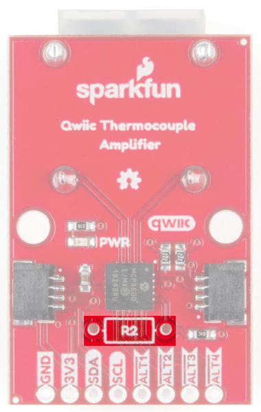 |
 |
|---|---|
| PCC Connector | Screw Terminal |
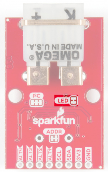
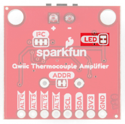
LED Jumper
Wanna turn off that pesky power LED? Cut this jumper.
 |
 |
|---|---|
| PCC Connector | Screw Terminal |
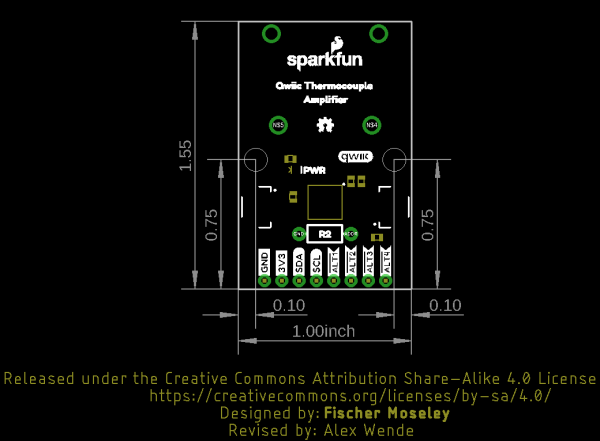
Board Dimensions
Feel free to click on either of the images below for a closer look!
 |
 |
| Qwiic Thermocouple Amplifier PCC | Qwiic Thermocouple Amplifier Screw Terminals |