SparkFun Qwiic AS3935 Lightning Detector Hookup Guide
This Tutorial is Retired!
This tutorial covers concepts or technologies that are no longer current. It's still here for you to read and enjoy, but may not be as useful as our newest tutorials.
View the updated tutorial: SparkFun AS3935 Lightning Detector Hookup Guide (v20)
 Elias The Sparkiest
Hardware Overview
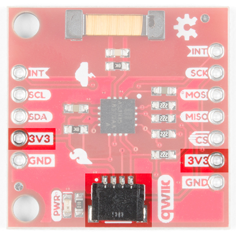
Power
You can provide 3.3V through the Qwiic connector on the board or through the 3V3 labeled pin on the through hole header. When you correctly power the board, the on board power LED will turn on.
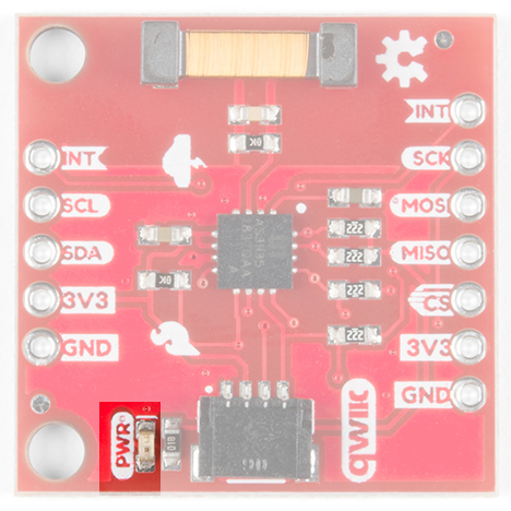
LED
There is one red LED on the product that will turn on when power is supplied to the board. You can disconnect this LED by cutting the jumper on the underside of the product labeled LED.
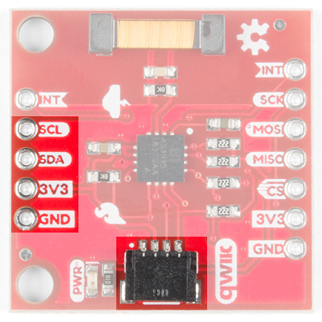
Qwiic Connector or I2C Pins
There is one Qwiic connector on the board to easily connect to the sensor via I2C. If you prefer the old school method of connecting to the I2C pins, we've also broken out those four pins on the side of the board as plated through holes.
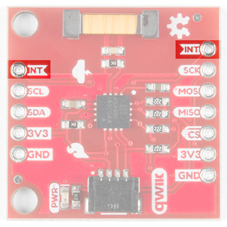
Interrupt Pin
The interrupt pin turns high when the lightning detector has sensed an event, whether it's lightning, a disturber, or noise. Make sure to connect to this pin to check if there is an event detected.
Jumpers
There are four jumpers on this product all on its underside.
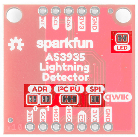
From left to right starting at the bottom: there are two address jumpers labeled ADR that allow you to change. The default I2C address is 0x03 but it can be changed to three other options: 0x02, 0x01, 0x00. We recommend 0x03 and 0x02, but if you really know what you're doing then you can also use 0x01 or 0x00. These two addresses are reserved for special I2C commands and you can read more about I2C addressing from this article.
Next to the two address jumpers are the I2C pull-up resistor jumpers. If you have many I2C devices chained together you may have to cut these jumpers. Next to that you, have the SPI jumper that enables SPI when closed. Finally, in the upper right is the power LED disconnect jumper. If that power LED is irritating or unnecessary, then cut that jumper.
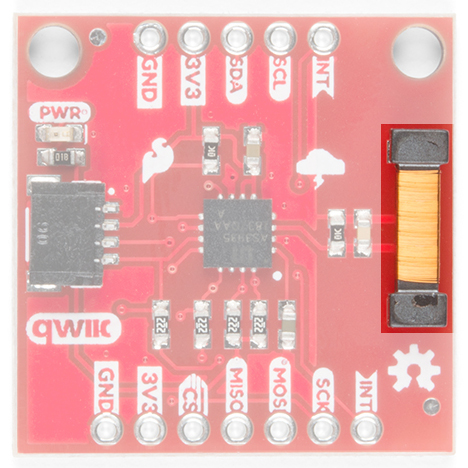
Antenna
The large-ish part on the board is the board's antenna. Keep the area around the antenna free as it is what picks up lightning events. With that said, check below for some common sources of false positives and noise.
False Positives and Noise
There are a number of sources that can cause false positives but the lightning detector itself can reliably filter these out by default. If not, there are a number of settings you can configure using the lightning detector library to increase the chip's robustness to noise and false positives. However, it can help to know some potential sources of noise (from the AS3935 fact sheet) fluorescent lighting, microwave ovens, and switches. From the datasheet, it states that smartphone and smartwatch displays, and DC-DC converters can also trigger as noise. Keep in mind that you would probably have to put your lightning detector on top of your phone for it to register. I found that using the lightning detector in the office was near impossible because I'm surrounded by at least ten computers, three 3D-printers, and numerous soldering irons.