SparkFun Pulse Oximeter and Heart Rate Monitor Hookup Guide
Introduction
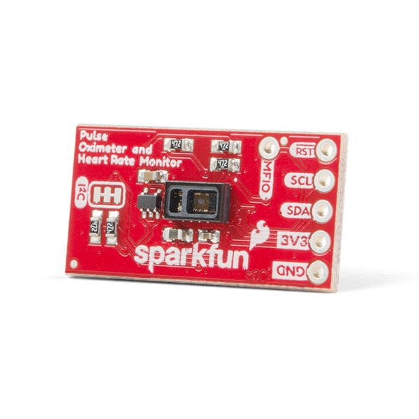
The SparkFun Pulse Oximeter and Heart Rate Monitor is an I²C based biometric sensor. Utilizing two chips from Maxim Integrated, the SparkFun Pulse Oximeter and Heart Rate Monitor has both the MAX30101 biometric sensor and MAX32664 biometric hub. While the former does all the sensing, the latter is an incredibly small and fast Cortex M4 processor that handles all of the algorithmic calculations, digital filtering, pressure/position compensation, advanced R-wave detection and automatic gain control. We've combined them and written an Arduino Library with example code demonstrating basic to advanced features to help get you started utilizing the SparkFun Pulse Oximeter and Heart Rate Monitor into your next project. Or if you're looking to put these IC's into a final product, Maxim has provided some features to get FDA approval. Let's get started!
Required Materials
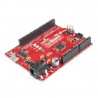
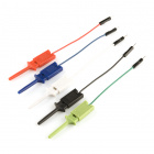
To follow along with the example code used in this tutorial, you will also need the following materials. You may not need everything though depending on what you have. Add it to your cart, read through the guide, and adjust the cart as necessary.
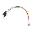
Qwiic Cable - 100mm
PRT-14427If you need different size Qwiic cables, we offer a kit that contains many sizes but we also carry them individually as well. Make sure to use a Qwiic cable of sufficient length for flexibility. Short lengths like the 50mm Qwiic cable can be harder to obtain sensor readings.
Qwiic Cable - 100mm
PRT-14427Qwiic Cable - Breadboard Jumper (4-pin)
PRT-14425Qwiic Cable - 500mm
PRT-14429Suggested Reading
Our Qwiic ecosystem keeps growing and growing with a host of new Qwiic enabled micro-controllers and sensors, check here for an overview.
 |
We would also recommend taking a look at the following tutorials if you aren't familiar with them.


