SparkFun ProDriver and Mini Stepper Motor Driver Hookup Guide
 QCPete, santaimpersonator
 Hardware Overview - Mini Stepper Motor Driver
Board Dimensions
Below, are basic drawings of the board dimensions and component layout for the SparkFun Mini Stepper Motor Driver. For more detailed measurements, users should download and open the KiCad files from the GitHub repository or from the Documents tab on the product page. It should be noted that the layout of the PTH breakout pins is compatible with breadboards and that the pins on the edge of the board, have a .10" spacing for headers (or to solder more permanent connections).

SparkFun Mini Stepper Motor Driver board dimensions. (Click to enlarge)
Power
Unlike the ProDriver, the Mini Stepper Motor Driver requires two power inputs:
3V3- Supplies the I/O voltage for the pull-up resistors on theM0-M3pins. Additionally, it is connected to a voltage divider that provides the reference voltage (VREF) for the drive current, limitation.VM- Powers the TC78H670FTG motor driver IC and supplies the output power for driving a bipolar stepper motor (or DC motors).
I/O Voltage Level
The 3.3V PTH connection provides the I/O voltage level for the pul-up resistors on the M0 - M3 pins. It is also used for the hardware configuration for the drive current, limitation on the TC78H670FTG.
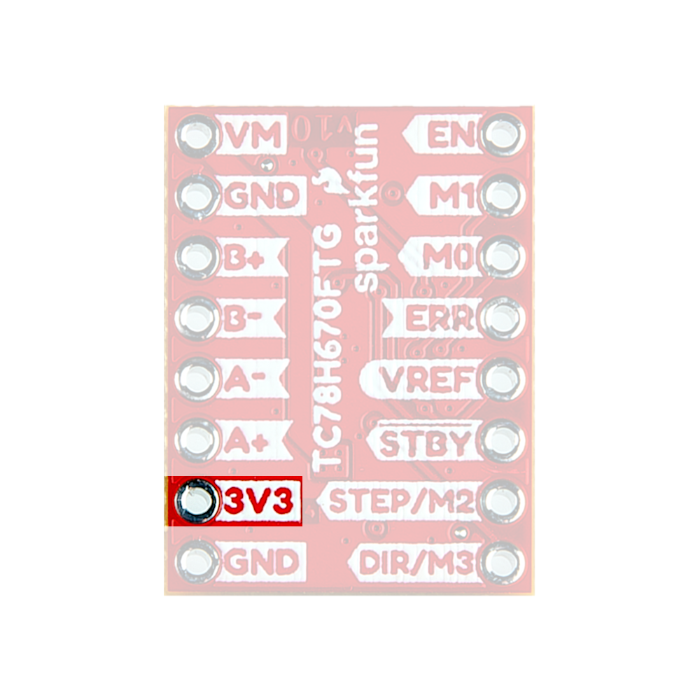
3V3 pin on the Mini Stepper Motor Driver. (Click to enlarge) VREF), which has a maximum input range of 1.8V and the resistor combination of the voltage divider, was calculated with the assumption that 3.3V would be provided.Motor
⚡ Note: Do not connect or disconnect the motor while the Mini Stepper Motor Driver is powered; as it may damage the motor driver IC.
In order to drive a motor, users will need a power supply with an voltage between 3.3 - 16V and can source at least 2A. Users will connect their power supply to the VM and GND pins on the Mini Stepper Motor Driver.

VM and GND pins on the Mini Stepper Motor Driver. (Click to enlarge) ⚡ Note: For the Mini Stepper Motor Driver, we recommend that users attach an electrolytic capacitor (>50µF) between the VM and GND pins.
Users that have a power supply with a DC barrel jack, may find some of these accessories useful:
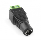
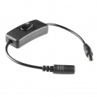
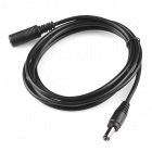
Pin Connections
The Mini Stepper Motor Driver was designed with PTH breakout pins in a compact layout that is compatible with breadboards.
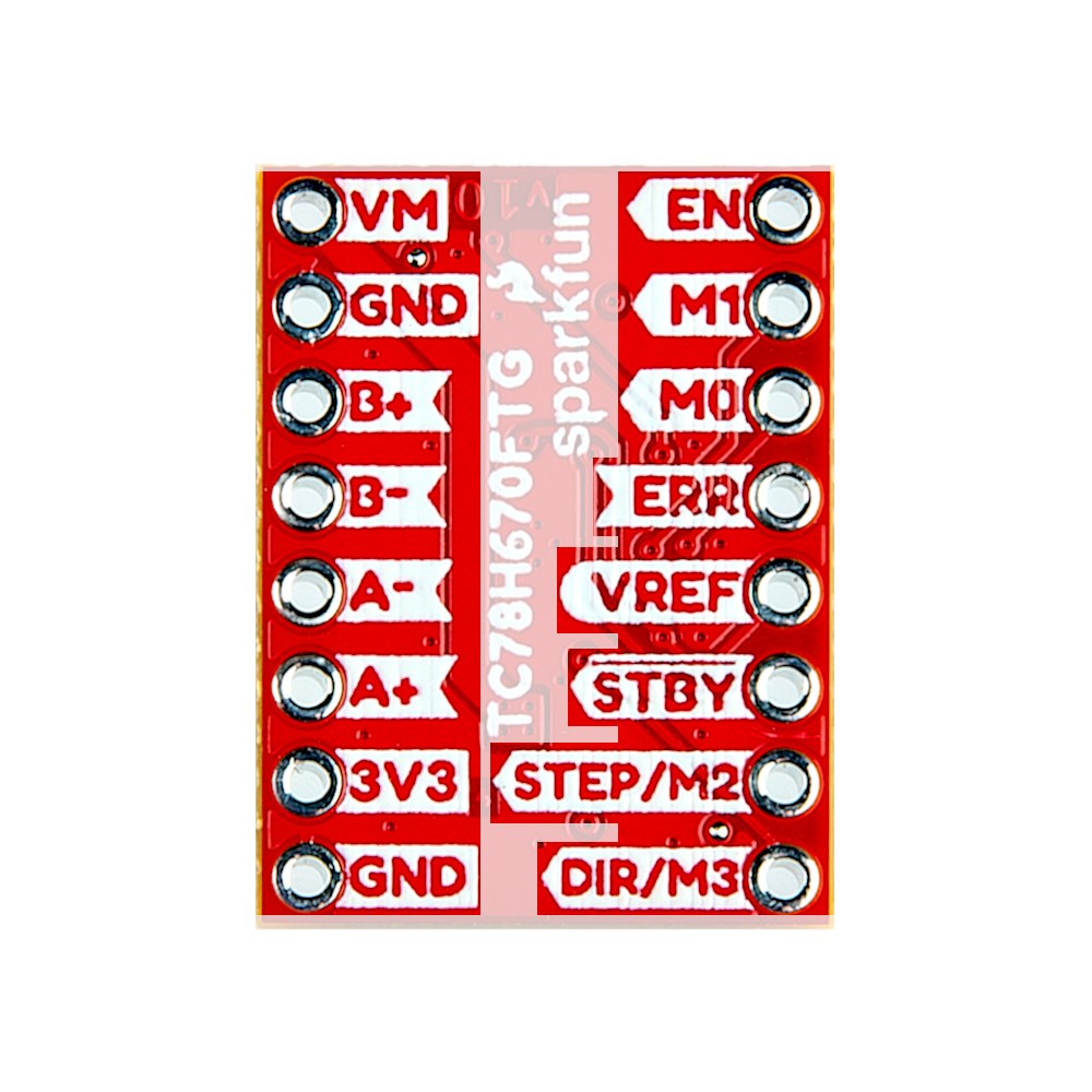
More details on these pins are laid out in the following sections below, excluding the power pins. Details for the 3V3 and VM pins are described in the power section above.
Input Control Pins
The input control pins are used to interface directly with the TC78H670FTG motor driver. For more details on the functions of the pins listed below, check out the datasheet for the TC78H670FTG.

| Pin Name | Label | Description | Operating Something |
|---|---|---|---|
| Ground Reference | GND |
Ground (i.e. the 0V reference) | 0V |
| Standby | STBY |
This pin is used to either place the motor driver in standby or initiate one of the control methods.
|
0 to 3.3V |
| Enable | EN |
When the motor driver is configured for clock-in stepping, this pin is used to enable the motor output ON or OFF.
|
0 to 3.3V (Default: Low or 0V) |
| Error Detection Flag Output | ERR |
If a thermal shutdown (TSD), over current (ISD), or motor load
open (OPD) error, is triggerd, the pin output is pulled low. Under a normal operating status, the level of ERR pin is equal to the EN control voltage from outside. The error flag can be released by reconnecting the VM power or by setting the device to standby.
|
0 to 3.3V |
|
MODE0 UP-DW (Clock-in) S_DATA (Serial) |
M0 |
MODE0: Utilized to configure the conrol method of the motor driver, when the standby pin is released. Based upon that control method, the pin will then function as one of the following inputs:
|
0 to 3.3V (Default: High or 3.3V) |
|
MODE1 SET_EN (Clock-in) LATCH (Serial) |
M1 |
MODE1: Utilized to configure the conrol method of the motor driver, when the standby pin is released. Based upon that control method, the pin will then function as one of the following inputs:
|
0 to 3.3V (Default: High or 3.3V) |
|
MODE2 CLK (Clock-in) S_CLK (Serial) |
STEP/M2 |
MODE2: Utilized to configure the conrol method of the motor driver, when the standby pin is released. Based upon that control method, the pin will then function as one of the following inputs:
|
0 to 3.3V (Default: High or 3.3V) |
|
MODE3 CW-CCW (Clock-in) |
DIR/M3 |
MODE3: Utilized to configure the conrol method of the motor driver, when the standby pin is released. The pin will then, only function as an input for clock-in stepping:
|
0 to 3.3V (Default: High or 3.3V) |
| 3.3V Input | 3V3 |
|
3.3V |
| Current Threshold Reference | VREF |
Connected to the 10 kΩ potentiometer that controls the maximum drive current to the stepper motor coils. Iout (max) = 1.1 × Vref (V) |
0 to 1.8 V
(assuming a 3.3V input voltage) |
VREF), which has a maximum input range of 1.8V and the resistor combination of the voltage divider, was calculated with the assumption that 3.3V would be provided.Output Channel Pins
The output channel pins are used to drive the coils of the stepper motor. The paired outputs are connected to the two H-Bridges of the motor driver.

⚡ Note: Do not connect or disconnect the motor while the Mini Stepper Motor Driver is powered; as it may damage the motor driver IC.
| Pin Name | Label | Description |
|---|---|---|
| Positive "A" Channel Output | A+ |
The "A" channel motor output (+) pin |
| Negative "A" Channel Output | A- |
The "A" channel motor output (-) pin |
| Positive "B" Channel Output | B+ |
The "B" channel motor output (+) pin |
| Negative "B" Channel Output | B- |
The "B" channel motor output (-) pin |
For basic information on stepper motors, users should check out our Motors and Selecting the Right One tutorial. Additionally, we have included a few YouTube videos, below, that help explain the theory of the stepping functionality behind stepper motors. Users who have stepper motors with more than four wires, may also find this article enlightening.
Motors and Selecting the Right One
TC78H670FTG Motor Driver
The Mini Stepper Motor Driver operates with the Toshiba TC78H670FTG stepper motor driver. The TC78H670FTG is a 2-phase stepping motor driver, intended for bipolar stepper motors. The chip features two H-Bridge motor drivers that provide users with step size resolutions ranging from full steps, half steps, and micro-stepping down to a 1/128 of a step. The TC78H670FTG can be controlled with the standard clock-in stepping, but it also has an additional option for serial communication.
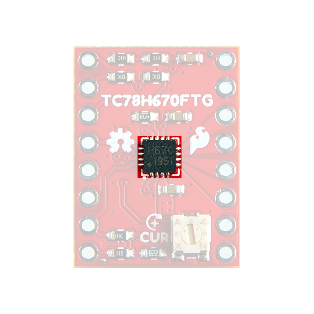
Some of the advantages to the TC78H670FTG over a simple H-Bridge, include a standby function, selectable mixed decay, error detect flag output, clock- in stepping or serial communication control, software control of the current output, and a minimal parts bill of matierals (BOM). The serial command method is especially unique because it allows users to precisely control the phase, torque, current limit and mixed decay ratio of each coil during the motor operation. Additionally, while in most stepper motor driver ICs, an external trimpot is required to set the current limit; however, with the Mini Stepper Motor Driver, a simple serial command can be utilized to precisely adjust the current limit.
| Characteristic | Description |
|---|---|
| Motor Power Supply Voltage: | 2.5 to 16.0V |
| Output Current: | 2.0A (max) |
| Control Methods: |
|
| Clock Frequency: |
|
| Step Size Resolution: |
Discrete Steps
Micro-Steps
|
| Error Detection Functions: |
|
Enable/Error Pin Functionality
On the Mini Stepper Motor Driver the EN and ERR pins are broken out separately; however, these connections are tied to the same pin on the TC78H670FTG, which operates as a control input and output for error flags. A typical application of the EN/ERR pin with a microcontroller is displayed below.
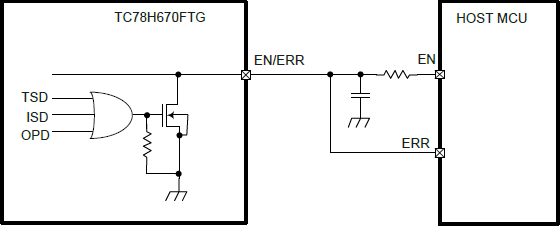
EN/ERR pin application from the datasheet. (Click to enlarge) This duality allows the TC78H670FTG to give users control of the power to the motor drive channels; while also providing autonomous functionality to disable its own power, when an error flag is triggered and simultaneously, provide an output indicator on the same pin.

EN and ERR pins on the Mini Stepper Motor Driver. (Click to enlarge) H-Bridge Power Control
The EN pin controls the ON/OFF operation of the H-Bridges to the motor outputs. When the EN pin is low, all of the H-Bridge MOSFETs turn off and become high impedance (Hi-Z). Likewise, when the EN pin is set high, the motor channel outputs will be driven normally, based on the stepping controls.
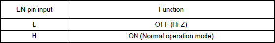
EN pin functionality from the datasheet. (Click to enlarge) VM power-on and power-off cycles by setting the EN pin low to disable the motor channel outputs. The EN pin can be set high after the power supply reaches the target voltage and becomes stable.Error Detection
The TC78H670FTG has a built-in functionality to detect thermal shutdown (TSD), over current (ISD), or motor load
open (OPD) connection issues. When these errors are triggered, the ERR pin is pulled low. In a normal operating status, the level of ERR pin is equal to the EN control voltage from outside. After the error is triggered, the error flag can be released by reconnecting the VM power or by setting the device to standby.
Standby Function
The standby pin for the TC78H670FTG, is used to set up the control method for the motor driver. When the standby pin is low, the motor is released from any control methods and is in standby. On the up edge, of when the standby pin is set high, the motor driver is configured for clock-in stepping or serial communication control based on the input state of the M0, M1, M2, and M3 pins.

HIGH. Pulled from the datasheet. (Click to enlarge) Control Methods
There are two different communication or control methods for users to interface with the Mini Stepper Motor Driver. The control method is configured by the input state of the M0 - M3 pins, when the TC78H670FTG is released from standby mode. The TC78H670FTG features the common clock-in stepping method and a more unique serial communication control.
Serial Communication Control
This method is unique to the TC78H670FTG Toshiba motor driver. The control logic allows users to manipulate registers through serial communication, which provide control over:
- The motor rotation direction (or polarity)
- Maximum current output, torque
- OPD error detection
- Selectable mixed decay (used to finely tune drive current to the motor)
- Driving the motor rotation (full steps only).
(*For more details on the configuration options for the available registers, refer to Section 9 of the datasheet.)
Clock-In Stepping Control
This is a standard method for controlling most stepper motor drivers. By default, the Mini Stepper Motor Driver is configured for clock-in stepping in the fixed mode with a step resolution of 1/128 of a step.
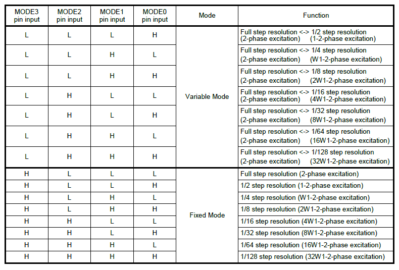
- Step Resolution Modes
With the clock-in control method, users can set up how the step resolution is configured. TC78H670FTG has the two modes for the step resolution settings, a variable mode and a fixed mode. These modes are also initiated by the input states of theM0-M3pins after releasing the standby pin, when the clock-in control method is configured. Below, is a table from the datasheet of the step resolution settings.- Variable Mode: The motor can be started with full step resolution and the step resolution can be changed while the motor is operating.
- Fixed Mode: Once initiated, the step resolution is configured and maintained during the motor operation.
Once clock-in stepping and the step resolution are configured together. The TC78H670FTG awaits for the up-edge of the clock (CLK) signal, for the STEP/M2 pin, to before it shifts the motor’s electrical angle per step. The DIR/M3 pin, controls the clockwise/counter-clockwise (CW-CCW) rotation direction of the motor for clock-in stepping.
- When the
DIR/M3pin is low, the motor is driven with a counter-clockwise (CCW) operation. - Like wise, when the
DIR/M3pin is high, the motor is driven with a clockwise (CW) operation.
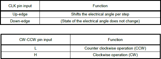
DIR/M3 (CLK) and STEP/M2 (CW-CCW) pin functionality for clock-in stepping, from the datasheet. (Click to enlarge) Step Resolution Transition
In variable mode, users can transition between different ranges of step size resolutions with the M0 and M1 pins. To enable the transition between step size resolutions, the M1 (SET_EN) pin must be high, when the TC78H670FTG is in variable mode for clock-in stepping. The M0 (UP-DW) pin is used to control the direction of the step size transition.
- When the
M0pin is low, the step size resolution is increased to a smaller step size (i.e. from 1/4 to 1/8 of a step). - Like wise, when the
M0pin is high, the step size resolution is decreased to a larger step size (i.e. from 1/8 to 1/4 of a step).
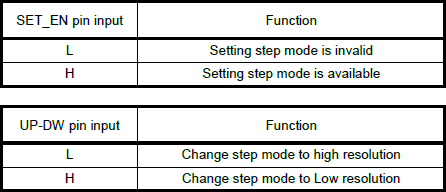
M1 (SET_EN) and M0 (UP-DW) pin functionality for transitioning the step size resolution during clock-in stepping, from the datasheet. (Click to enlarge) The transition between step size resolutions occurs, synchronously with the up-edge of the next clock signal. It should also be noted, that the transition can only change the step size resolution one increment at a time (i.e. it takes three clock cycles to transition from a 1/4 step size, down three sizes, to a 1/32 step size resolution).
Maximum Drive Current
The maximum drive current for the Mini Stepper Motor Driver is limited to 2A (max). However, the peak output current can be controlled with two different methods.
Hardware: The first method controls the drive current through the reference voltage (Vref). The reference voltage, can be configured utilizing the external potentiometer or VREF breakout pin.

VREF pin that can be utilized to control the maximum drive current. For the hardware control, the maximum drive current can be calculated with the following equation:
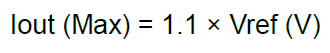
Software: The second method controls the drive current through software. Utilizing serial communication to the TC78H670FTG, the registers can be configured to limit the maximum drive current. The maximum drive current can be calculated with the following equation, based on the configured registers:

Chopping Current Drive
Chopping is a technique that is used to control the average current per phase, by rapidly switching a relatively high output voltage to the motor coils, on and off. This technique improves the current rise time in the motor and improves the torque at high speeds, while maintaining a high efficiency in the constant current drive.
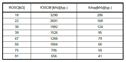
On the TC78H670FTG, the OSCM oscillation frequency (fOSCM) and chopping frequency (fchop) are adjusted with an external resistor (ROSC), connected to the OSCM pin. On the Mini Stepper Motor Driver, a 47 kΩ resistor is utilized.