SparkFun ProDriver and Mini Stepper Motor Driver Hookup Guide
 QCPete, santaimpersonator
 Hardware Assembly
Hardware Connections
Latch Terminals
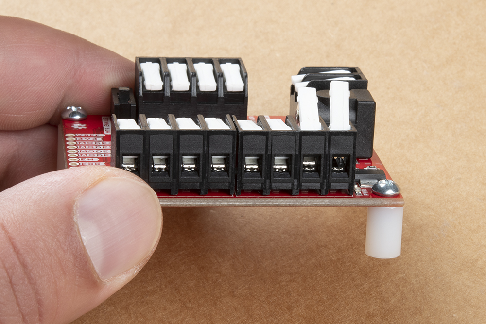
When working with the latch terminals of the ProDriver, users should be aware of the following, about the clamping mechanism:
- If you look closely at the closed jaws or clamping mechanism, you will notice a small gap. Just like screw terminals, there is a minimum and maximum wire thickness for the jaws to physically clamp onto wires.
- On some stepper motors, you may need to tin (i.e. add a little solder) the wire leads and thicken the wires just enough to be clamped.
- Make sure you are inserting the wire between the jaws.
- Looking to the right end of the picture, below, on the latch partially closed, it should be noted that is possible to accidentally insert a wire above the jaws.
Headers
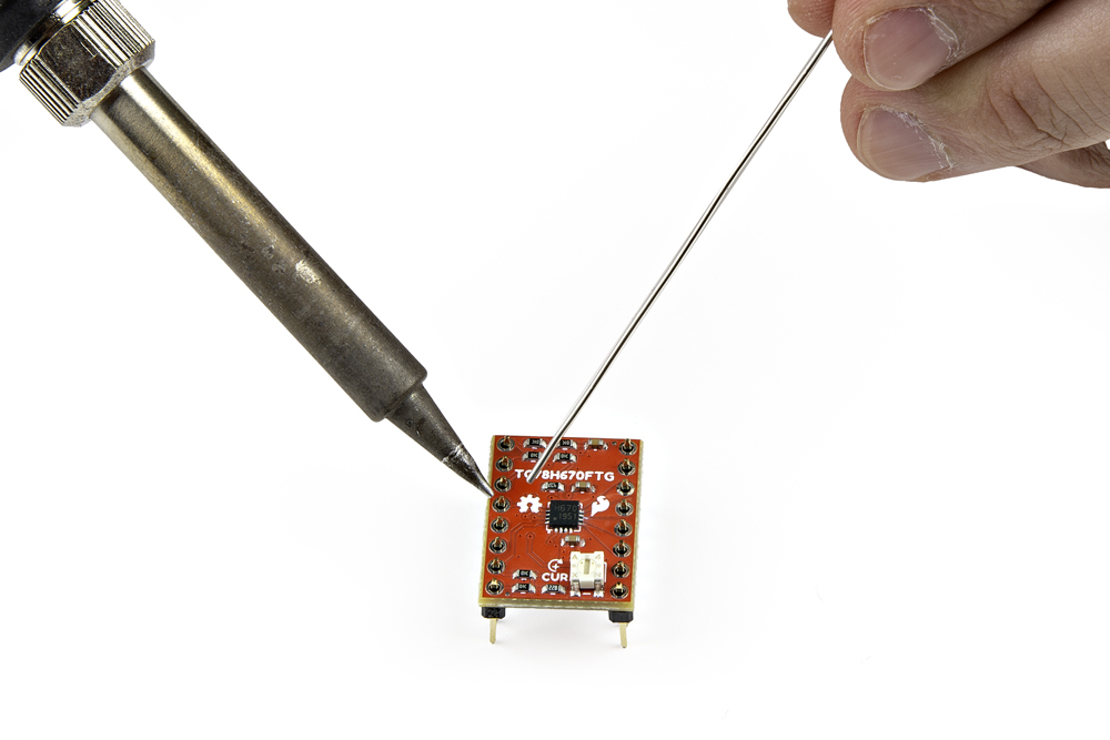
When prototyping, users may consider soldering headers to the ProDriver or Mini Stepper Motor Driver. Most users may consider solder headers to the Mini Stepper Motor Driver, as the pin layout is compatible with breadboards.
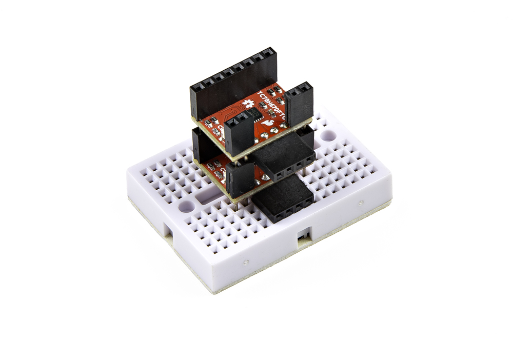
When connecting Mini Stepper Motor Drivers in parallel, users may find it more convenient to utilize our stackable headers.
Hookup Wires
For a more permanent connection, user may choose to solder their connections directly to the ProDriver or Mini Stepper Motor Driver.

Power Connections
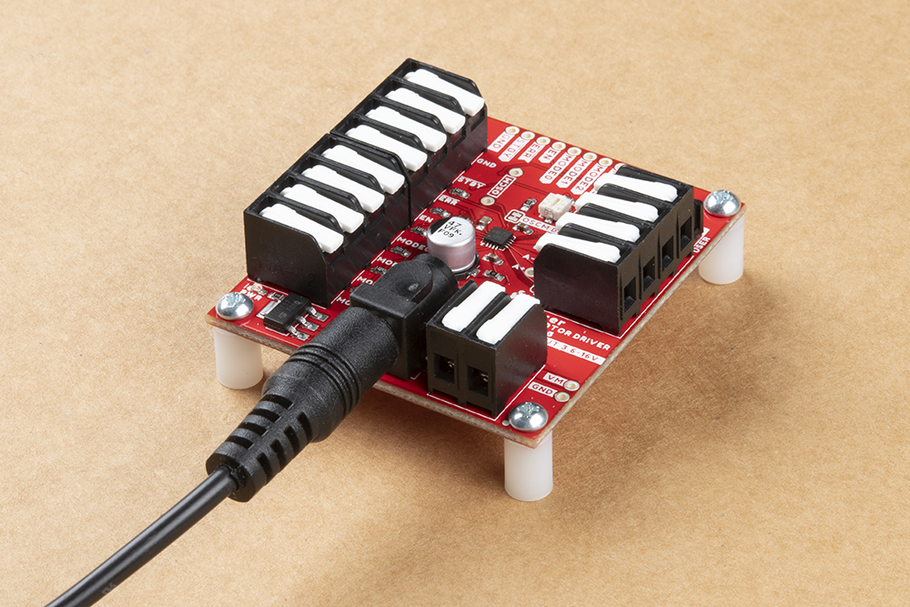
On the Prodriver, we recommend one of our wall adapter, power supplies to connect to the DC barrel jack. Otherwise, users can utilize the (VM and GND) PTH or latch pins to attach an external power supply.
On the Mini Stepper Motor Driver, users can connect an external power supply to the VM and GND PTH pins. When prototyping with a breadboard, we recommend using either the regulated power from a development board or utilizing a barrel jack adapter.

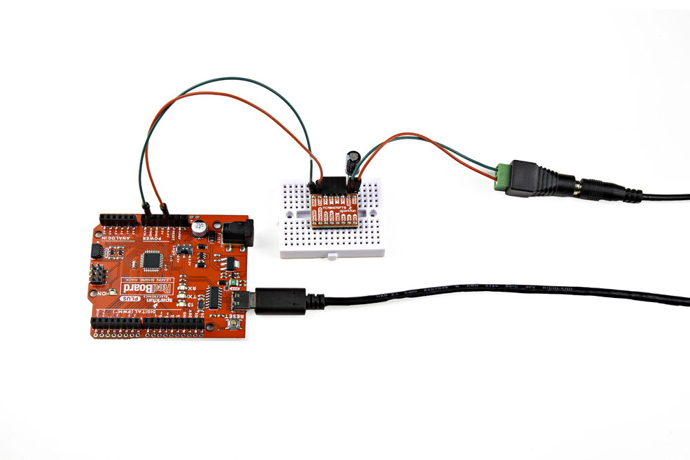
⚡ Note: For the Mini Stepper Motor Driver, we recommend that users attach an electrolytic capacitor (>50µF) between the VM and GND pins.
Input Control Pin Connections
The input control pins need to be connected to a microcontroller. To utilize the Arduino examples below, without modifying the code, we recommend using the SparkFun RedBoard (Qwiic) as the microcontroller. Use the table and image below to hookup a SparkFun RedBoard to the ProDriver or Mini Stepper Motor Driver with some jumper wires.
| ProDriver Control Pins | STBY |
EN |
MODE0 |
MODE1 |
MODE2 |
MODE3 |
ERR |
|---|---|---|---|---|---|---|---|
| Mini Stepper Motor Driver Control Pins | STBY |
EN |
M0 |
M1 |
STEP/M2 |
DIR/M3 |
ERR |
| RedBoard Pins | D8 |
D7 |
D6 |
D5 |
D4 |
D3 |
D2 |
MODE 1/M1 pin. Each motor driver board requires a seperate pin on the microcontroller to operate their MODE 1/M1 pin. (See the example below)Motor Channel Output Connections
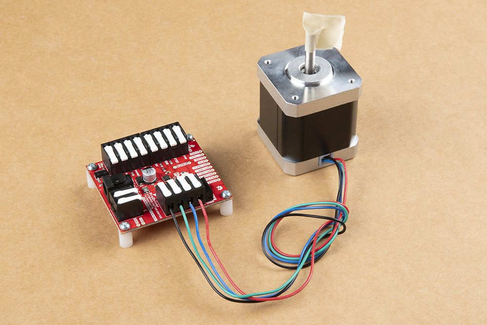
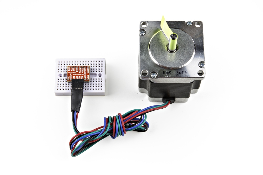
The output channels for the H-Bridges need to be connected to the stepper motor. Users need to hookup the wire pairs for each coil to individual channels. However, the polarity of the connections isn't very important as the direction of the motor rotation can be controlled in software. For the recommended stepper motor, use the table and image below to hookup the motor to the ProDriver or Mini Stepper Motor Driver.
| Motor Driver Output Channels | A+ |
A- |
B+ |
B- |
|---|---|---|---|---|
| Stepper Motor Wires | Black | Green | Red | Blue |
⚡ Note: Do not connect or disconnect the motor while the motor driver is powered; as it may damage the TC78H670FTG IC.
Motor Coil Pairs
In order to determine the wire pairs for each coil on their stepper motor, users can refer to the datasheet for the stepper motor. Often, the relevant information is indicated as shown in the diagram below.
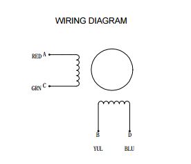
For a 4-wire motor, users can alternatively use a multimeter to determine the wire pairs for the coils. This is done by comparing the resistance of one wire and against each of the three remaining wires. Whichever wire shows the lowest resistance against the first wire is the pair mate. The remaining two wires should show similar resistance between the two of them.
Examples
Single Stepper Motor
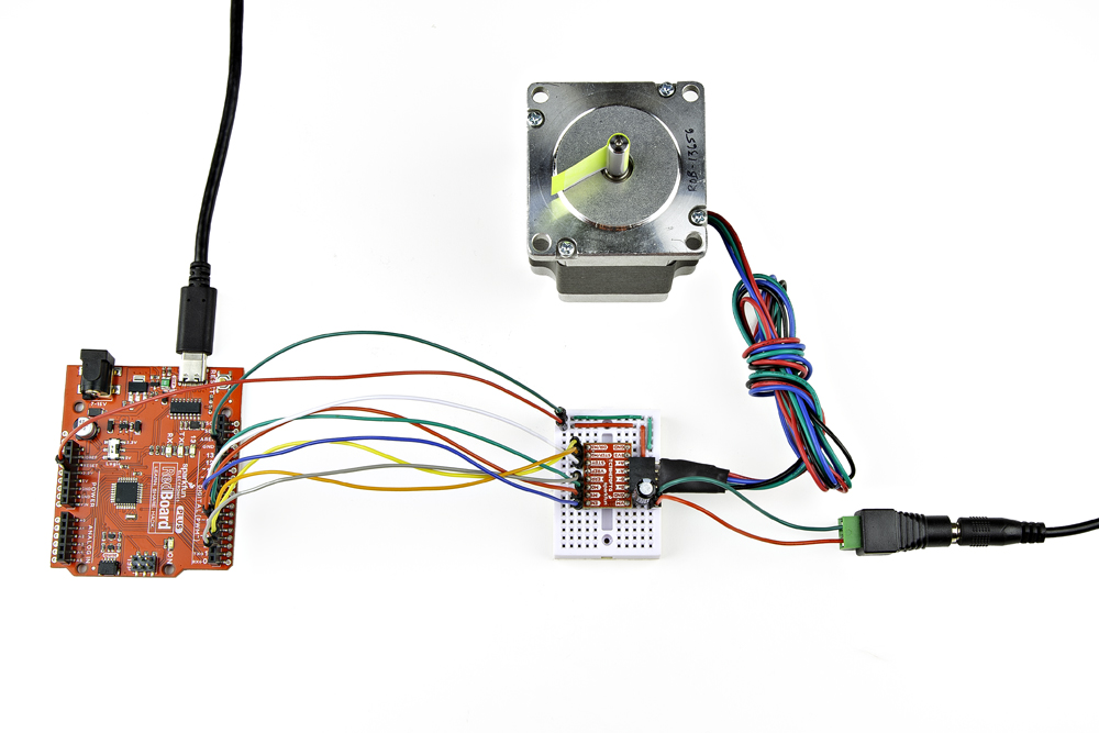
Utilizing the instructions above, an example of the standard assembly used for most of the examples in the Arduino library, is shown below.
The SparkFun RedBoard connected to a ProDriver and stepper motor. (Click to enlarge)
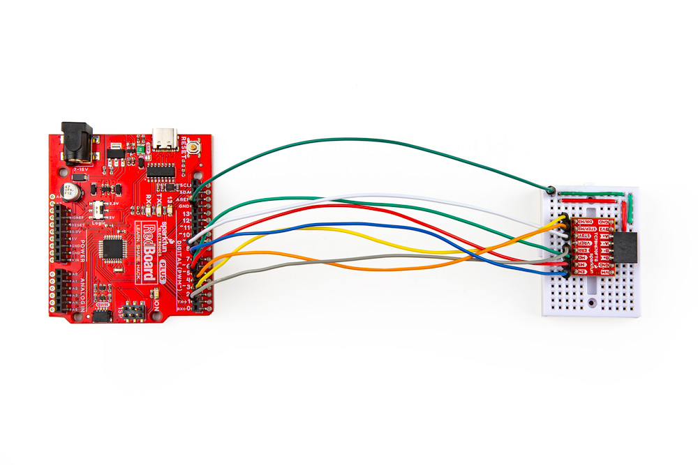
The SparkFun RedBoard connected to a Mini Stepper Motor Driver and stepper motor. (Click to enlarge)
| ProDriver Control Pins | STBY |
EN |
MODE0 |
MODE1 |
MODE2 |
MODE3 |
ERR |
|---|---|---|---|---|---|---|---|
| Mini Stepper Motor Driver Control Pins | STBY |
EN |
M0 |
M1 |
STEP/M2 |
DIR/M3 |
ERR |
| RedBoard Pins | D8 |
D7 |
D6 |
D5 |
D4 |
D3 |
D2 |
Multiple Stepper Motors
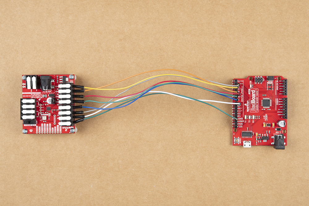
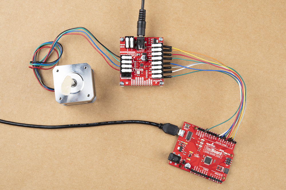
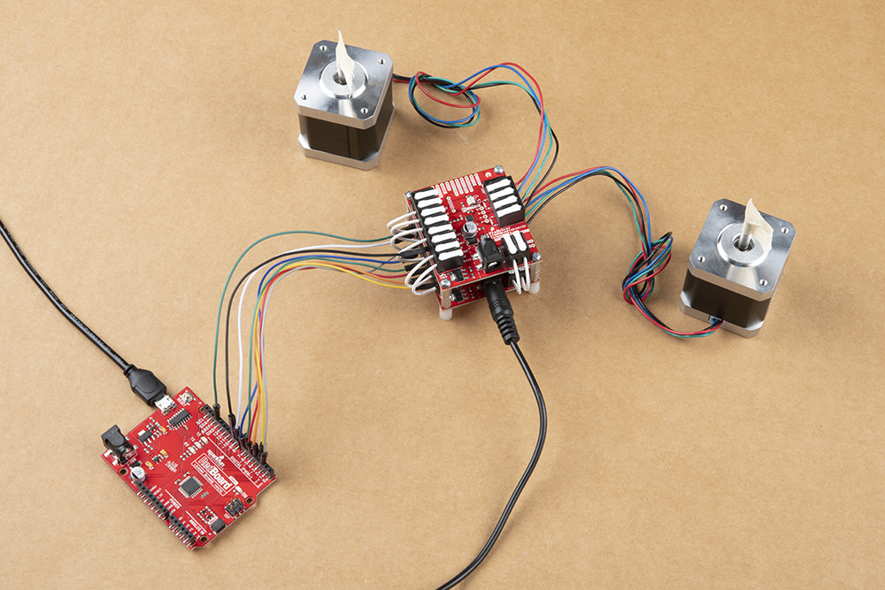
For users interested in utilizing multiple stepper motors, we have provided an additional Arduino example for hooking up two Mini Stepper Motor Driver(s) and/or ProDriver(s) in parallel. Use the table and image below to hookup the SparkFun RedBoard to the two motor drivers with some jumper wires.
Two ProDrivers

Two Mini Stepper Motor Drivers

Combination
MODE 1/M1 pin. Each motor driver will utilizes a different pin on the RedBoard, for their MODE 1/M1 pin.| Motor Driver (1) | STBY |
EN |
MODE0
M0
|
MODE1
M1
|
MODE2
STEP/M2
|
MODE3
DIR/M3
|
ERR |
|
|---|---|---|---|---|---|---|---|---|
| Motor Driver (2) | STBY |
EN |
MODE0
M0
|
MODE1
M1
|
MODE2
STEP/M2
|
MODE3
DIR/M3
|
ERR |
|
| RedBoard | D8 |
D7 |
D6 |
D5 |
D9 |
D4 |
D3 |
D2 |