SparkFun PIR Breakout Hookup Guide
Hardware Assembly
Assembling the PIR Breakout circuit is pretty straight-forward since the board only has three pins. Recommended setup requires some soldering so if you are not familiar with through-hole soldering or want a refresher, we suggest reading through this tutorial:
How to Solder: Through-Hole Soldering
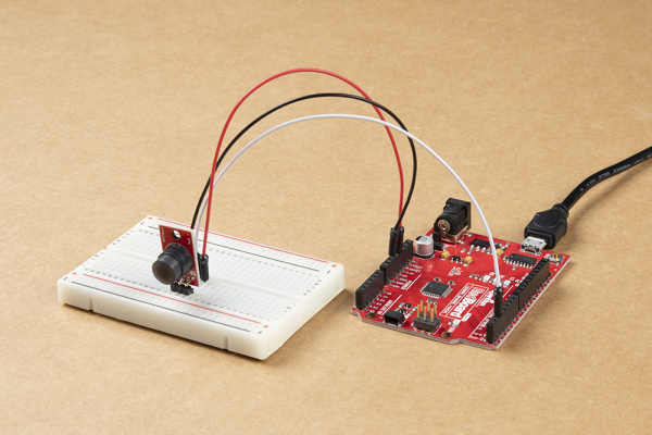
The demo circuit we'll assemble for the PIR Breakout uses a standard breadboard, M/M Jumper Wires and a SparkFun RedBoard Qwiic along with the SparkFun PIR and a set of breakaway male headers - right angle.
For permanent installations, we recommend soldering wire directly to the PIR Breakout to create a strong and stable connection to the sensor. For some tips on preparing and soldering wire, take a look at this tutorial:
Working with Wire
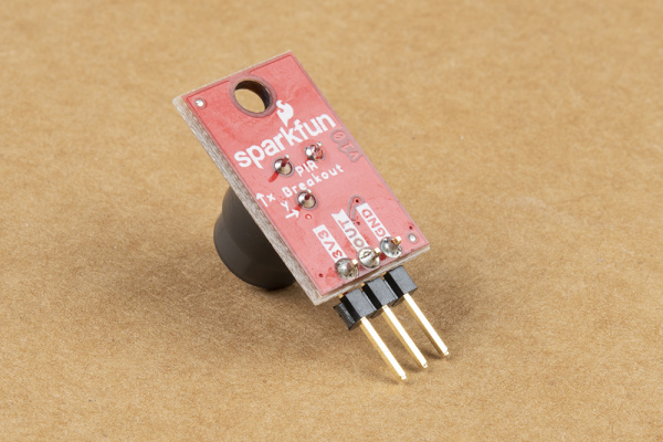
To start off, we break off three pins from the set of breakaway male headers and solder them to the PTH header on the PIR Breakout to have the sensor stand perpendicular to the breadboard for easy testing.
Next, we plug the sensor into the breadboard (users connecting directly to their microcontroller can ignore this step) taking care to orient it properly so the pins are not sharing the same rail. After the PIR is in place, select three jumper wires and connect the PIR's pins to the matching pins on the microcontroller. 3.3V to 3.3V, GND to Ground/GND and OUT to a digital I/O pin.
- EKMC4607112K: 3.0 to 6.0V
- EKMB1107112: 2.3 to 4.0V
The OUT signal from the SparkFun PIR can also be used as an external interrupt to trigger an interrupt event on a microcontroller. Users who wish to use the PIR as an external interrupt should note which digital I/O pins on their microcontroller are interrupt-capable and connect the PIR's OUT to one of those pins. For this example, we'll connect the OUT pin to a digital pin that is also interrupt capable: D2.
If you are using a Raspberry Pi or other SBC/development-board that uses Python as its primary programming language, follow the above assembly steps for the PIR and connect it to your Pi/SBC's GPIO header taking care to make the proper pin connections. Raspberry Pi users looking for a quick GPIO reference can find one here or you can use the pinout command from the GPIO Zero Python Library in the console to display the pinout there.

