SparkFun Line Follower Array Hookup Guide
 MTaylor
Introduction
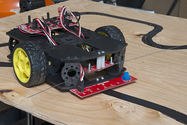
The Line Follower Array is is an array of eight IR sensors that are configured and read as digital bits! In our laboratories, the RedBot shadow chassis was used as a test platform, but this product was designed as an add-on for any bot. The array features visible LEDs, so you can see what the robot sees, brightness control right on the board, and an I2C interface for reading and power control.
Features
- 8 sensor eyes (QRE1113, like in our line sensor breakout)
- I2C interface
- Adjust IR brightness on the fly with a knob
- Switch IR on and off with software
- Switch visual indicators on and off with software
- Invert dark/light sight with software
- Based on the SX1509 I/O expander
Covered In this Tutorial
This tutorial will help get the line follower array connected to your bot with the Arduino IDE over I2C. It is split into the following sections:
- Hardware Overview -- An overview of the physical board and electrical characteristics.
- Hardware Assembly -- Attaching the sensor to a 328p based micro.
- Setting the Jumpers -- Describes the board's jumper configurations.
- Installing the SparkFun Line Follower Array Arduino Library -- Where to get the library for the array.
- Core Functions of the Arduino Library -- Describes the basic reading and configuration of the array.
- Extra Library Function: The Circular Buffer -- The library has a hidden feature! Use a circular buffer to log data for computation.
- Example Sketches -- Test out the sensor on your desk or try a line following example on your robot.
Suggested Reading
The array acts as a stand alone I2C device pretty well. If you want to learn more about I2C or are using the RedBot kits, check out this additional material.
- I2C Communication -- The array is controlled over an I2C interface. Learn what that is here.
- RedBot Experiment Guide -- Using the RedBot with red or black chassis? Work through some experiments first in order to get going.
- Line following experiment -- One of the experiments for the RedBot is line following with only three sensors. Working through this experiment revels why eight sensors is better.
- Counting and Converting in Binary -- The sensors correspond to bit positions in a byte. Rusty on conversions? Take a look here.
Hardware Overview
The array PCB has a few pieces to note.
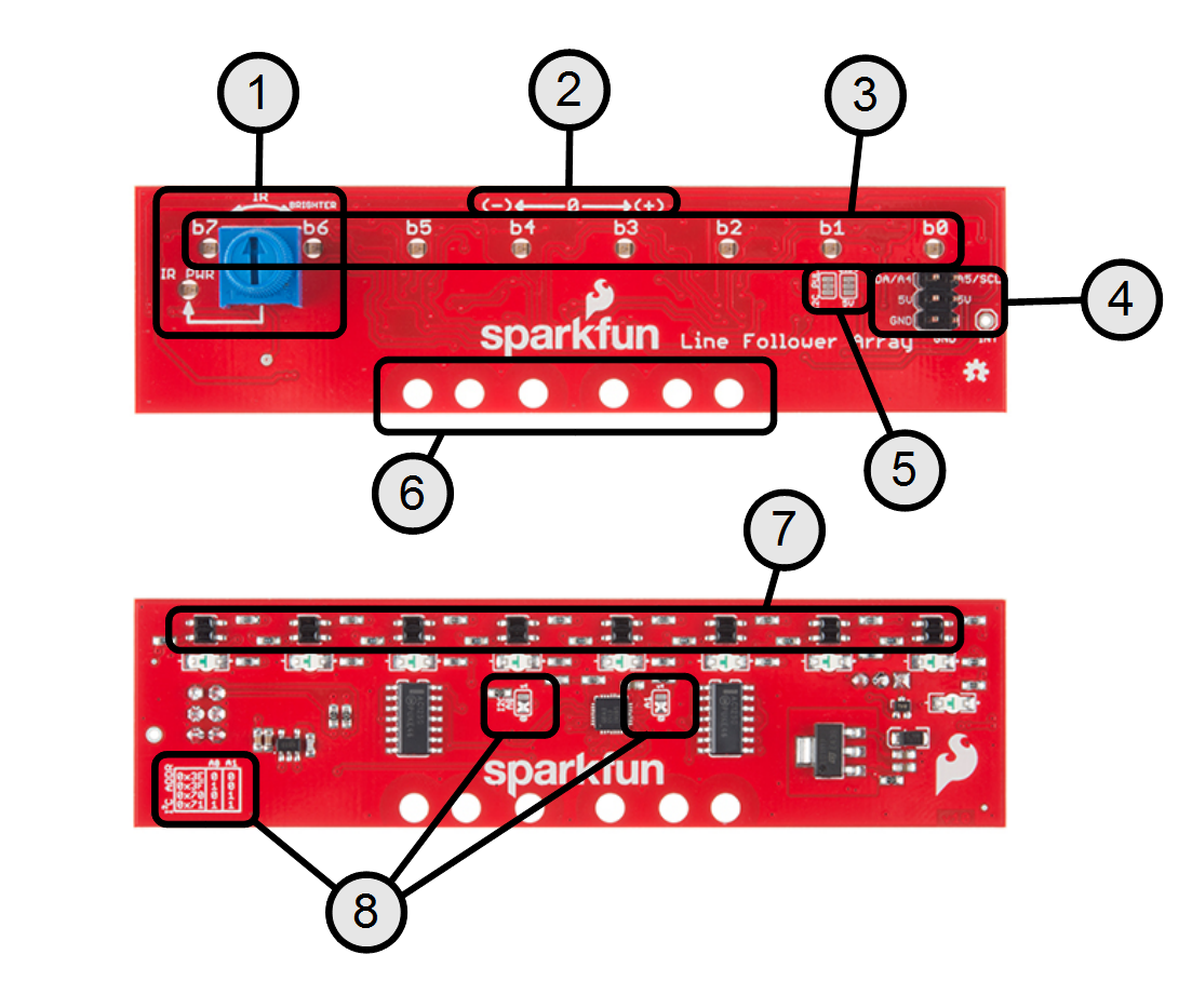
- IR brightness control and indicator -- The IR PWR led shows the strength of the IR LEDs. Brighter means more IR emitted.
- Polarity marking -- Shows getPosition() polarity.
- Robot vision indicators -- See what the IR sensors are picking up. Note: these are not inverted by the library's set/clearInvertBits() functions. Usage covered in Setting the Brightness
- Digital interface -- Described in the Assembly section.
- I2C pull option jumper -- Defaulted to 3.3V pull-up. Can be converted to 5V if necessary. See Setting the Jumpers.
- Mounting holes -- The inner two holes fit the Shadow chassis. Others are general purpose.
- The IR transducers -- These emit and detect IR radiation.
- I2C address selection -- Set the jumpers in accordance with the table for a desired address.
Electrical Specifications
| Parameter | Conditons | Min | Typ. | Max | |
|---|---|---|---|---|---|
| Supply Current |
Vcc = 5.0v Strobing disabled |
25 |
185 |
mA | |
| Vcc = 5.0v Strobing enabled Running 'MostBasicFollower' |
16 | 100 | 160 | mA | |
| Read Cycle TIme |
Vcc = 5.0v Strobing Enabled |
3.2 |
ms |
||
| Vcc = 5.0v Strobing Disabled |
250 | us |
Setting the Jumpers
The array has two configurable options: I2C address and I2C pull-up voltage.
I2C address
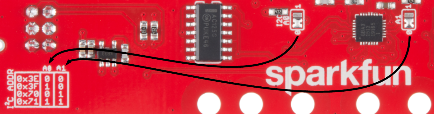
If you need to change the address of the array, move the solder jumper to set A0 and A1. The silkscreen table gives a reference. Seen in the photo, the default address is 0x3E. For example, if you want to use address 0x70, move A1 to the '1' position and leave A0 at '0'.
I2C pull-up voltage

The I2C bus of the array is pulled up to 3.3V by default. This should work for 3.3V and 5V boards, but if you need to change it explicitly to 5V, cut the copper bridge and add a solder jumper to the "5V" side. The other jumper is included if you need to disconnect the I2C bus from the pull-ups entirely. This will only be used in specific situations, for instance if the microcontroller side has strong pull-ups and the array's resistors need to be disabled.
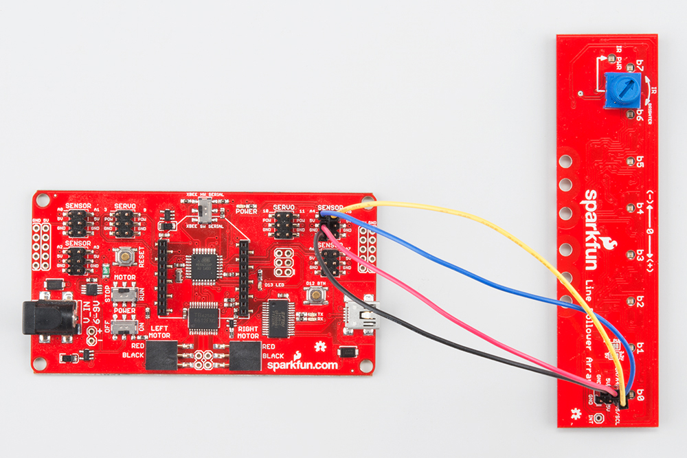
Assembly
Assembly is super easy! Make the following connections with your microcontroller.
| Signal/Description |
Line Follower Silkscreen |
RedBot Mainboard Silkscreen |
RedBoard Silkscreen |
|---|---|---|---|
| Power - 5v DC |
5V |
5V | 5V |
| Ground | GND | GND | GND |
| I2C Data |
SDA/A4 | A4 | A4 or SDA |
| I2C Clock |
A5/SCL |
A5 | A5 or SCL |
| INT(*) | NC | NC | NC |
* Note: INT pin is not required but can be connected to any input if the interrupt functionality is programmed into the SX1509 expander.


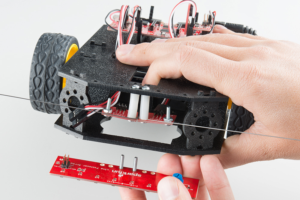
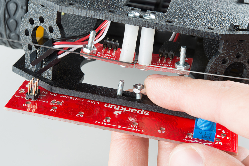
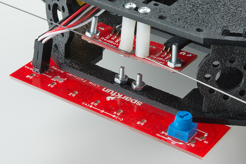
Mechanical Attachment to a Shadow Chassis
Attaching to the Shadow Chassis happens through the slot where the original three line following sensors were placed. Put 4-40 hardware through the array and hold with a finger. Hold the bolts through the slot in the shadow chassis, thumb on the 4-40 nuts, then make the electrical connections.
Installing the Arduino Library
The sensor bar is basically an I2C expander with sensors, but to simplify implementation we've created a set of drivers to collect the data in a convenient way. Visit the GitHub repository to download the most recent version of the library, or click the link below:
For help installing the library, check out our How To Install An Arduino Library tutorial. You'll need to move the SparkFun_Line_Follower_Array_Arduino_Library folder into a libraries folder within your Arduino sketchbook.
Run a test example
To verify that your hookup works, load up the "RedBot Line Follower Bar Arduino Library\ReadBarOnly" by going to File > Examples > RedBot Line Follower Bar Arduino Library > ReadBarOnly.
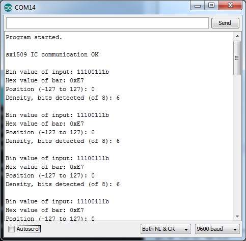
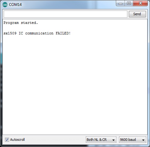
The default values set by this sketch should work for a fresh, out-of-the-box sensor. Set the baud rate to 9600, and run the sketch. You should see the Arduino output data every second in a few different formats. If the sketch only says that the IC communication failed, double check your wiring connections.
Setting the Brightness
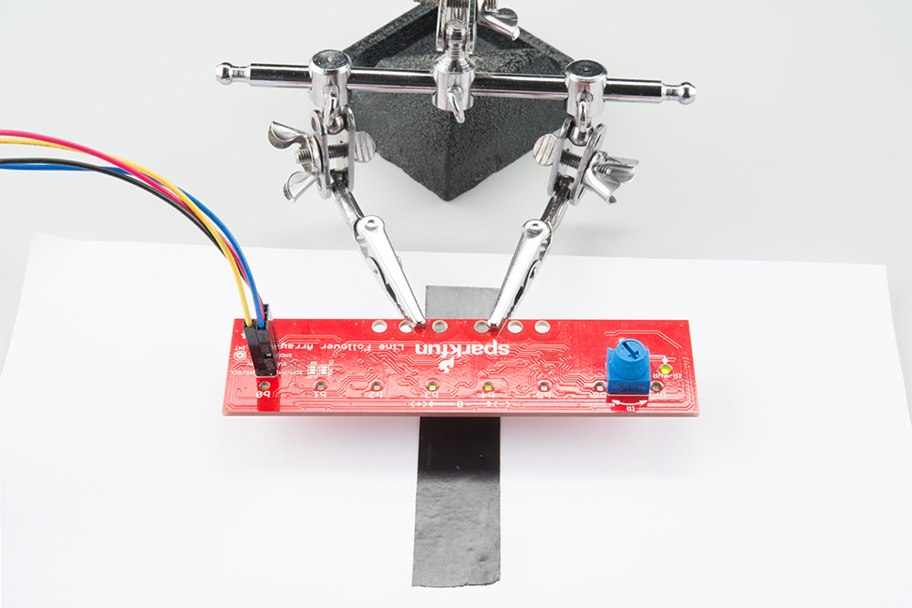
The knob on the sensor array is used to set the brightness of the IR LEDs. Because silly humans can't see IR, the "IR PWR" LED is provided to give feedback for how bright the LEDs are operating, and to indicate that the regulator is functioning. This indicates what the brightness will be even if the IR illuminators are disabled in firmware.
Follow these three steps to configure the IR brightness.
Step 1: Turn the brightness down until light areas stop picking up.
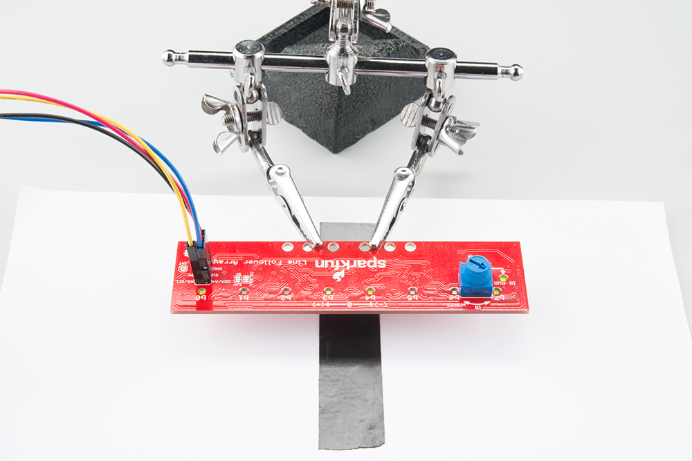
Step 2: Turn the brightness up until dark areas start falsely picking up.
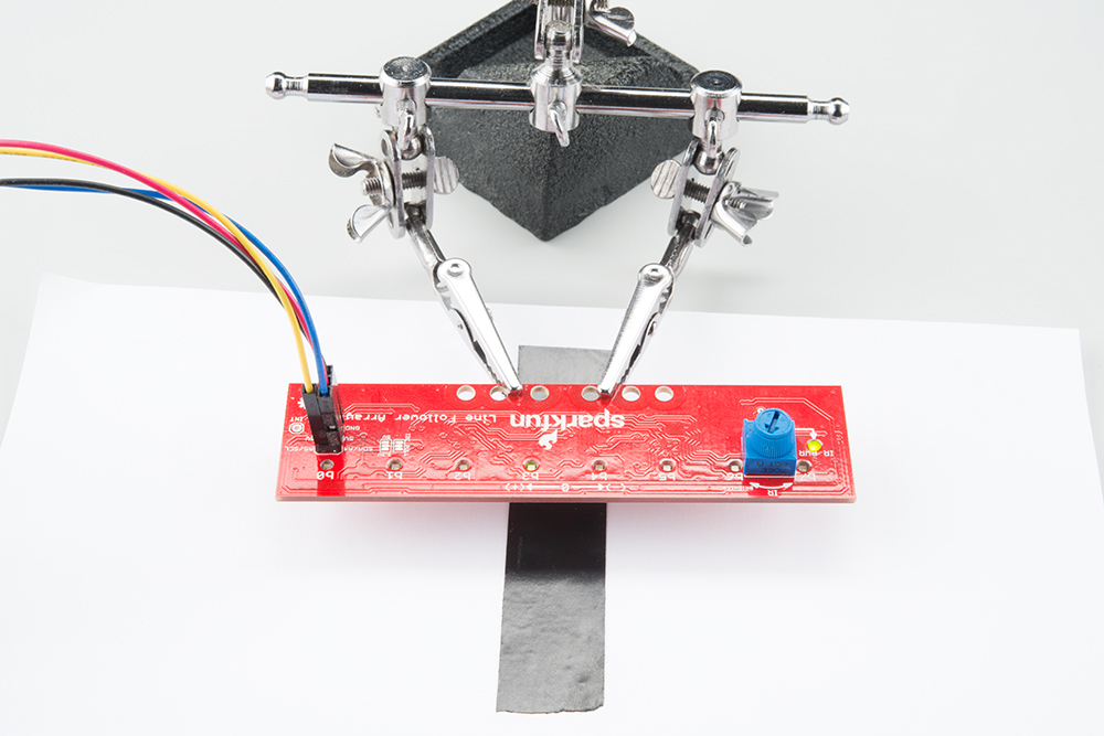
Step 3: Set the brightness somewhere between those two points.
Core Functions of the Arduino Library
The basic library has the following parts
Object construction
Each instance of the SensorBar library needs to be constructed in the global scope for all to access.
Arguments:
Pass the device address in HEX ( unsigned 8 bit ).
Example:
For the default address of 0x3E:
SensorBar mySensorBar( 0x3E );
begin()
Use begin to start the sensor bar's I2C expander. This use Wire.h under the hood.
begin() takes no arguments.
Return:
Returns success message (unsigned 8 bit).
returns 1 if it was able to communicate with the sensor bar or 0 if it had troubles. In the example ReadBarOnly the sketch is held if the sensor did not respond.
After .begin(); has been run, the sensor bar is ready to start reading data. Place it in the setup() section to run once.
Example:
language:c
uint8_t returnStatus = mySensorBar.begin();
if(returnStatus)
{
  Serial.println("sx1509 IC communication OK");
}
else
{
  Serial.println("sx1509 IC communication FAILED!");
}
Serial.println();
getRaw()
Get a reading from the array as a single 8 bit word where each bit represents an IR sensor. If the sensor's lights show: ON, ON, ON, ON, OFF, ON, ON, ON, this function will return 0xF7 matching the bit positions on the silkscreen. If InvertBits has been set though, the result will be 0x08.
Notice that the silkscreen labels b7 through b0 represent the same bits of this raw data.
getRaw() takes no arguments.
Return:
Returns the states of the IR detectors, as bits of a byte (unsigned 8 bit).
Example:
language:c
//Get the data from the sensor bar.
uint8_t rawValue = mySensorBar.getRaw();
Get the states and place in the temporary variable rawValue
getPosition()
Use to get the data as as a vector to the average of detected points. Returns a signed 8 bit number, -127 to 127.
For example, if the center two bits (b4 and b3) detect line, the average will be 0, or centered. If the left four (b7 through b4) detect line, the result will be an average to the left (-79). If only the left most sensor detects line, b7, the result will be -127. Use the silkscreen axis on the sensor bar to assist interpretation.
Note that if InvertBits does not match the line/field colors, the result of getPosition() will not have meaning. This is because multiple detected positions get averaged to come up with a vector, and an inverted setting means basically all the positions are detected and average near zero (center).
getPosition() takes no arguments.
Return:
Position as a signed 8 bit integer, ranged: -127 to 127.
Example:
language:c
//Print the position
Serial.print("Position (-127 to 127): ");
Serial.println(mySensorBar.getPosition());
getDensity()
Use to get the number of sensors that are detecting a line.
This is useful for detecting validity of the perceived line or to detect stop conditions, such as if the robot has been picked up.
getDensity() takes no arguments.
Return:
Returns an 8-bit unsigned integer ranged 0 through 8.
Example:
language:c
//Print the density
Serial.print("Density, bits detected (of 8): ");
Serial.println(mySensorBar.getDensity());
setBarStrobe() and clearBarStrobe()
Use to turn on and off the bar's IR strobing to save power.
setBarStrobe() and clearBarStrobe take no arguments and return void.
Example:
language:c
//For this demo, the IR will only be turned on during reads.
mySensorBar.setBarStrobe();
//Other option: Command to run all the time
//mySensorBar.clearBarStrobe();
Also note that a read operation takes 2-3x longer with BarStrobe set, as the library has to enable and disable the LEDs. If extremely rapid reads are required, clear the BarStrobe.
setInvertBits() and clearInvertBits()
Use to reverse the perceived line/field color scheme. With inversion cleared, the sensor is looking for a dark line on light background. With inversion set, it looks for a light line on a dark background.
setInvertBits() and clearInvertBits() take no arguments and return void.
Example:
language:c
//Default dark on light surface
mySensorBar.clearInvertBits();
//Other option: light line on dark
//mySensorBar.setInvertBits();
Extra Library Function: The Circular Buffer
The arduino library actually contains two classes. The first (discussed above) does all the reading and configuration of the actual sensor. The second is a data structure for creating and holding a buffer of data.
The structure is a circular buffer where, when full, new data overwrites the oldest data and all access to the data is referenced from the newest piece of data.
Object Construction
Construct the buffer objects in the global scope.
Arguments:
Pass the maximum size of the buffer to create. Argument is type unsigned 16 bit integer, but size must be limited to the size of memory available.
getPosition() takes no arguments.
Example:
language:c
#define CBUFFER_SIZE 100

//...

CircularBuffer positionHistory(CBUFFER_SIZE);
getElement()
Read the data in the buffer at some depth from newest.
Arguments:
Pass the element number to get as unsigned 16 bit integer. The newest element is referenced as 0.
Return:
Element value as signed integer.
pushElement()
Add a new piece of data to the buffer.
Arguments:
Pass the value to push into the buffer as signed 16 bit integer.
pushElement returns void.
Example:
language:c
//Read data from the sensor and put it in the buffer.
positionHistory.pushElement( mySensorBar.getPosition());
averageLast()
Average some number of the most recent entries.
Arguments:
Pass number of elements to average as unsigned 16 bit integer.
Return:
The mathematical average of the newest elements as signed 16 bit integer.
Example:
language:c
//Get an average of the last 'n' readings
int16_t avePos = positionHistory.averageLast( 10 );
recordLength()
recordLenght() takes no arguments.
Return:
Number of elements currently in the buffer.
When working with a partially filled buffer, this will report how many entries have been pushed in. When the buffer is full, this reports the total size of the buffer.
Example Sketches
ReadBarOnly
This example exists to show all the forms of data collection that can be done with the library.
To use the sketch, select it from the 'examples' menu and load it onto an Uno compatible board. Open a serial terminal at 9600 baud and text of the raw data, position, and density should appear. Otherwise, it will proclaim that the communication has failed.
MostBasicFollower
This is an demonstration of line following capabilities using the RedBot mainboard and either chassis. It was designed for a dark line of about 3/4 inch width (spray paint or electrical tape) on a light background.
The sketch can navigate curved corners but not 90 degree corners! It's up to you to find a way to make it navigate. Also, this was designed to stop if the line is lost. There must be a way to seek partial line segments...
This example is being used in our demo video.
This sketch has a little state machine inside that reads the line, then goes to a state that calls drive functions, depending on some condition. It was designed to be simple on purpose. It's up to you to make a better system!
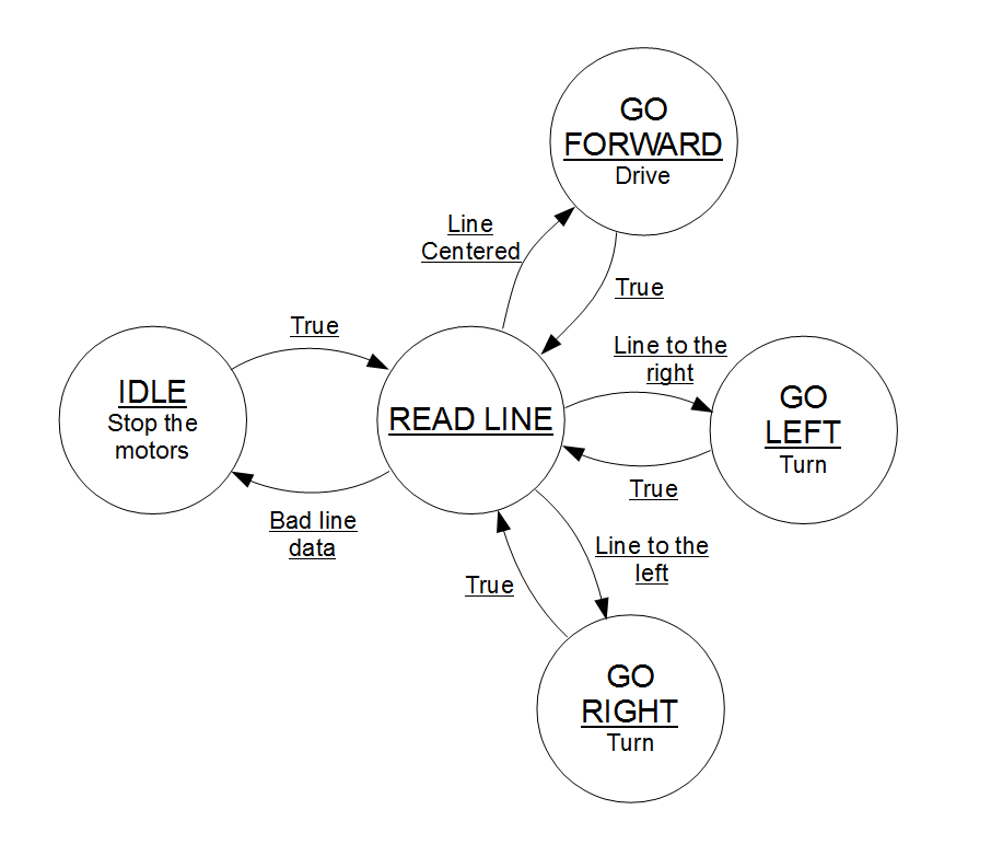
This blog post State Machines: blink.ino learns to snooze may help if you need a refresher on state machines.
AveragingReadBarOnly
This sketch was written to demonstrate how to get a pseudo-high resolution output from the array. Load the sketch and open a serial terminal at 115200 baud. The '*' is drawn on a scale as a rolling average filter of the getPosition() data.
It also allows you to look back in time to see what the robot previously went over.
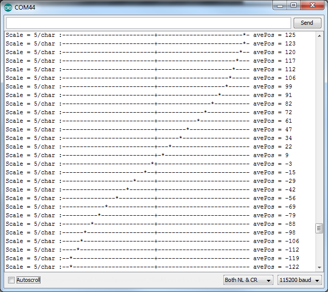
This works by creating a circular buffer which stores fresh getPosition() data at a regular intervals, and by averaging the newest 10 entries in the buffer.
The buffer class is included as an extra with the library. See The Circular Buffer section.
Resources and Going Further
Here are a few line following resources:
- SX1509 Hookup Guide -- You can treat the array as a SX1509 breakout board, use those drivers and fine tune your operation if you like.
- SX1509 Datasheet -- This datasheet describes the full operation of the I2C expander.
- PID tutorial -- Our Educator's pick for following lines with a PID (proportional, integral, differential) algorithm.
Happy line-following!