SparkFun GPS Dead Reckoning NEO-M8U Hookup Guide
 bboyho,
  Elias The Sparkiest
Hardware Overview
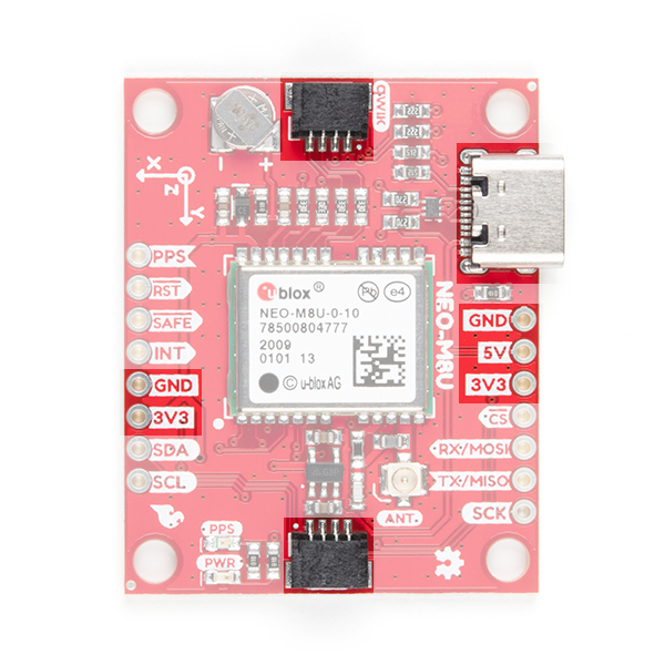
Power
Power for this board is 3.3V and we have provided multiple power options. This first and most obvious is the USB-C connector. Secondly, are the Qwiic Connectors on the top and bottom of the board. Thirdly, there is a 5V pin on the PTH header along the side of the board that is regulated down to 3.3V. Make sure that power your provide to this pin does not exceed 6 volts. Finally, just below the 5V pin is a 3.3V pin that should only be provided a clean 3.3V power signal.
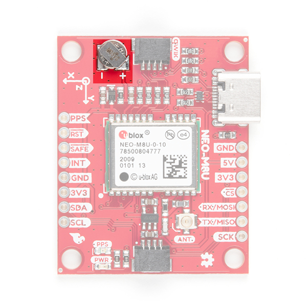
Battery
The small metal disk in the upper left corner is a small lithium battery. This battery does not provide power to the IC like the 3.3V system does, but to relevant systems inside the IC that allow for a quick reconnection to satellites. The time to first fix will about ~26 seconds, but after it has a lock, that battery will allow for about a 1.5 second time to first fix. This is known as a hot start and lasts for four hours after the board is powered down. The battery provides over a years worth of power to the backup system and charges slowly when the board is powered. To charge it to full, leave your module plugged in for 48 hours.
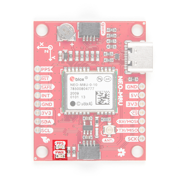
LEDs
There's is a red power LED just to the left of the bottom Qwiic connector and near the board's edge to indicate that the board is powered. There is another LED just above the power LED labeled PPS that is connected to the Pulse Per Second line. When connected to a satellite, this line generates a pulse that is synchronized with a GPS or UTC time grid. By default, you'll see one pulse a second.
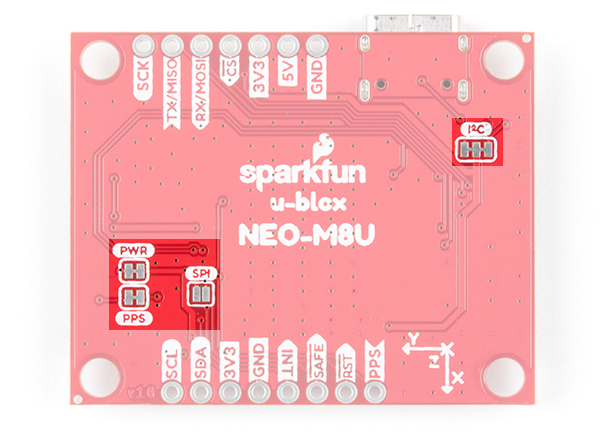
Jumpers
There are four jumpers on the underside of the product, each labeled with its function. At the upper right of the picture is a three way jumper labeled I²C that connects two pull-up resistors to the I2C data lines. If you have many devices on your I2C data lines, then you may consider cutting the two small traces connecting the center pad to the left and right pads. On the left side of the board is a jumper labeled PWR. If you cut this trace it will disconnect the Power LED. Just below is the PPS jumper that when cut disconnects the PPS LED. Finally, there's a jumper labeled SPI which enables the SPI data bus thus disabling the UART functions on those lines. For more information, check out our tutorial on working with jumper pads and PCB traces.
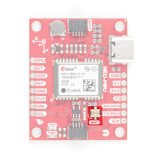
U.FL Connector
The SparkFun GPS NEO-M8U has a u.FL connector in which you can connect a patch antenna.
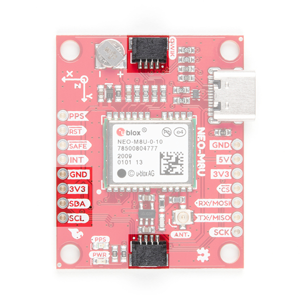
Qwiic and I2C
There are two pins labeled SDA and SCL which indicates the I2C data lines. Similarly, you can use either of the Qwiic connectors to provide power and utilize I2C. The Qwiic ecosystem is made for fast prototyping by removing the need for soldering. All you need to do is plug a Qwiic cable into the Qwiic connector and voila!
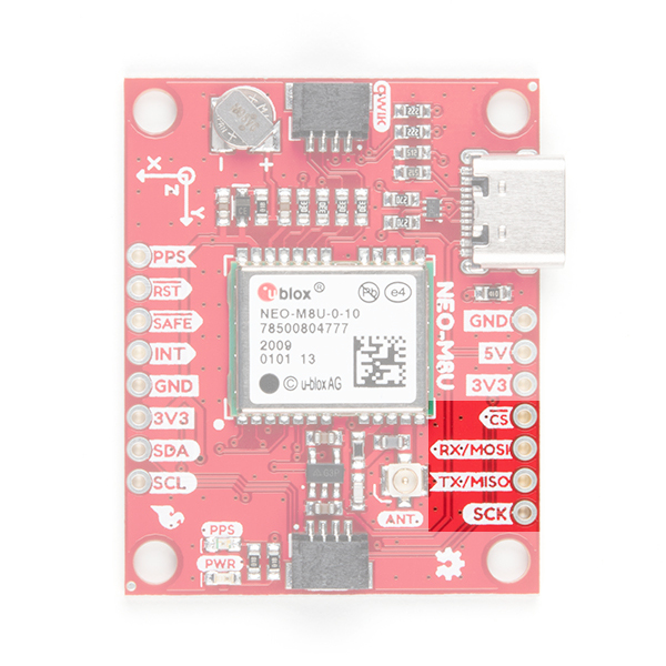
SPI
There are four pins on the right most header that are labeled with their corresponding SPI functionality. As mentioned in the jumpers section, you'll need to close the SPI jumper on the underside to enable SPI.
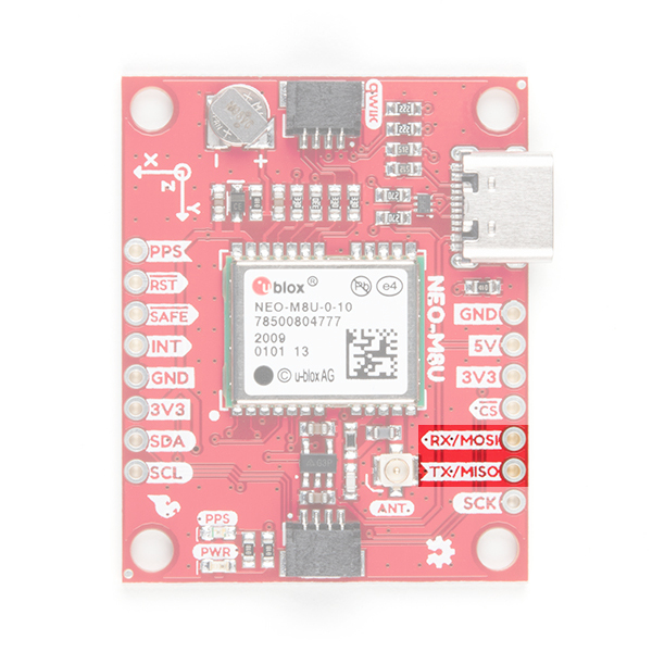
UART
There are two pins on the right most header labeled for their UART functionality.
Broken Out Pins
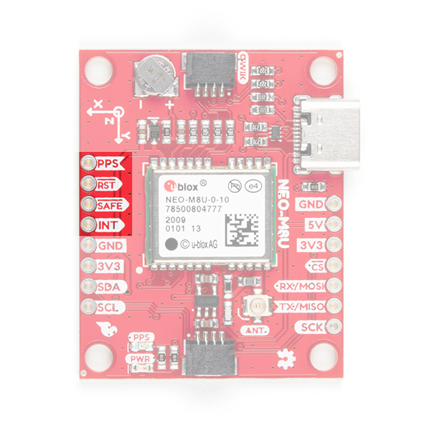
There are four other pins broken out: Pulse per second (PPS), Reset (RST), Safeboot (SAFE), and finally the interrupt pin (INT). The first pin PPS, outputs pulse trains synchronized with the GPS or UTC time grid. The signal defaults to once per second but is configurable over a wide range. Read the u-blox Receiver Protocol Specification in the Resources and Going Further tab for more information. The reset pin resets the chip. The next pin, SAFE is used to start up the IC in safe boot mode, this could be useful if you somehow manage to corrupt the module's Flash memory. The final pin INT can be used to wake the chip from power save mode.
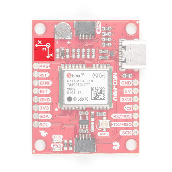
3D IMU Orientation and Reference
For easy reference, we've documented the IMU's vectors with 3D Cartesian coordinate axes on the top and bottom side of the board. Make sure to orient and mount the board correctly so that the NEO-M8U can accurately calculate navigation information. This is explained in detail in the Dead Reckoning Overview. Remember, it's all relative.
 |
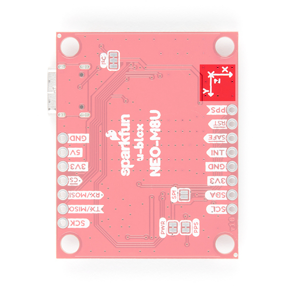 |
| Top View with the the Axis for Reference | Bottom View with the the Axis for Reference |
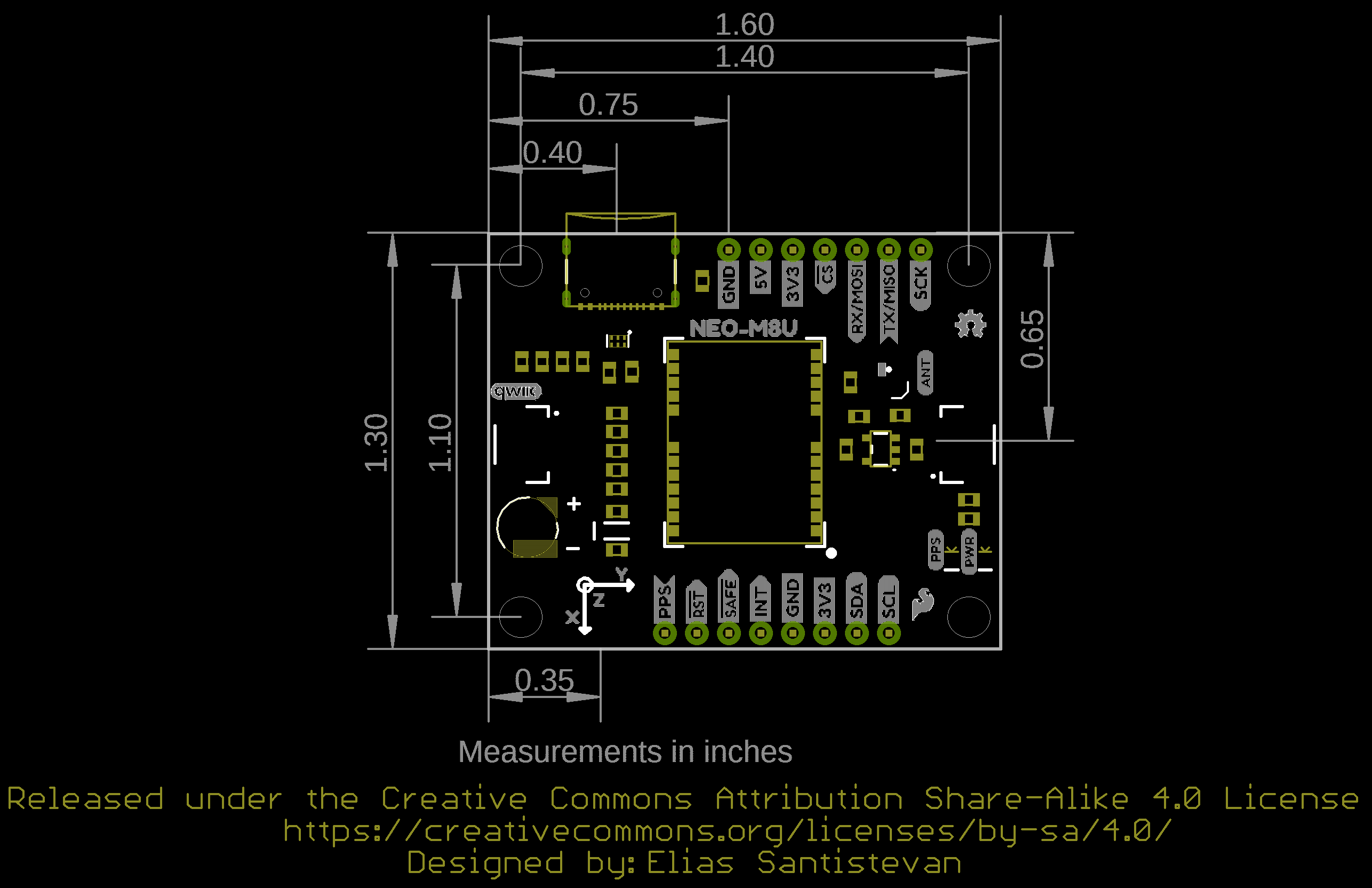
Board Dimension
Overall, the board is 1.30"x1.60".
GPS Capabilities
The SparkFun NEO-M8U is able to connect to up to three different GNSS constellations at a time. Below are the listed capabilities of the GPS unit taken from the datasheet when connecting to different GNSS constellations.
| Constellations | GPS+GLO | GPSL | GLO | BDS | GAL | |
|---|---|---|---|---|---|---|
| Horizontal Position Accuracy | Autonomus | 2.5m | 2.5m | 4.0m | 3.0m | To Be Confirmed |
| with SBAS | 1.5m | 1.5m | ||||
| Max Navigation Update Rate | PVT | 25Hz | 25Hz | 25Hz | 25Hz | 25Hz |
| Time-To-First-Fix | Cold Start | 24s | 25s | 26s | 28s | 29s |
| Hot Start | 2s | 2s | 2s | 2s | 2s | |
| Sensitivity | Tracking and Navigation | -160dBm | -160dBm | -160dBm | -160dBm | -154dBm |
| Reacquisition | -160dBm | -159dBm | -156dBm | -155dBm | -152dBm | |
| Cold Start | -148dBm | -147dBm | -145dBm | -143dBm | -133dBm | |
| Hot Start | -157dBm | -156dBm | -155dBm | -155dBm | -151dBm | |
| Velocity Accuracy | 0.05m/s | 0.05m/s | 0.05m/s | 0.05m/s | 0.05m/s | |
| Heading Accuracy | 1deg | 1deg | 1deg | 1deg | 1deg |