SparkFun GPS Breakout - XA1110 (Qwiic) Hookup Guide
Hardware Overview
Below is a table listing all of the hardware features and specs for the XA1110.
| Characteristic | Range |
|---|---|
| Operating Voltage | 3.3V: Regulated to 1.8V - 3.6V |
| Current | 25 mA (typical) |
| Hot/Warm/Cold Start | 1/5/15 seconds |
| Update Rate | 1 Hz (default), 0.1-10 Hz |
| I2C Interface | 100kHz & 400kHz (3.3V) |
| I2C Address | 0x10 |
| UART | 9600 bps (default), 4800-115200 bps (3.3V) |
| Position Accuracy | <3.0m, <2.5m with SBAS enabled |
| Satellites | 99 during search, 33 during tracking |
| Sensitivity | -148dBm Acquisition, -165dBm Tracking |
| Max Altitude | 80km (the mesosphere) using the example configuration sketch to enable high-altitude balloon mode |
| RTC Battery | 5.5mAh, enables warm start for 15 days without power |
Pins
The following table lists all of the XA1110's pins and their functionality.
| Pin | Description | Direction |
|---|---|---|
| GND | Ground | In |
| 3.3V | Power | In |
| SDA | Data | In |
| SCL | Clock | In |
| INT | Interrupt, goes low when NMEA data is ready, after packet is read, the pin pulls high | Out |
| Wake | Wake up | In |
| RST | Pulling low will reset the module | In |
| PPS | Provides one pulse-per-second signal | Out |
| RX | UART receiver; to receive commands | In |
| TX | UART transmitter; outputs GPS information | Out |
Optional Features
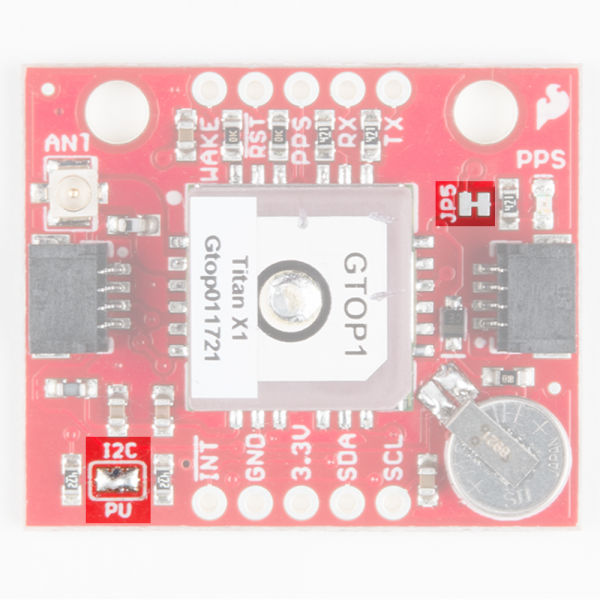
The XA1110 breakout has several optional features. The first of which is the option to disable the pulse-per-second LED. This can be done by slicing the connection on the JP5 jumper with a hobby knife. If multiple sensors are connected to the bus with the pull-up resistors enabled, the parallel equivalent resistance will create too strong of a pull-up for the bus to operate correctly. As a general rule of thumb, disable all but one pair of pull-up resistors if multiple devices are connected to the bus. If you need to disconnect the pull up resistors they can be removed by removing the solder on the pull up resistor jumper highlighted below. Both jumpers are shown in the below image.
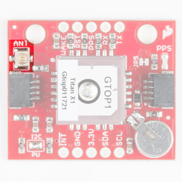
There is also a U.FL connector on the board, outlined below, which can be used in conjunction with the U.FL cable to connect to an external antenna

