SparkFun Blocks for Intel® Edison - Arduino Block
Introduction
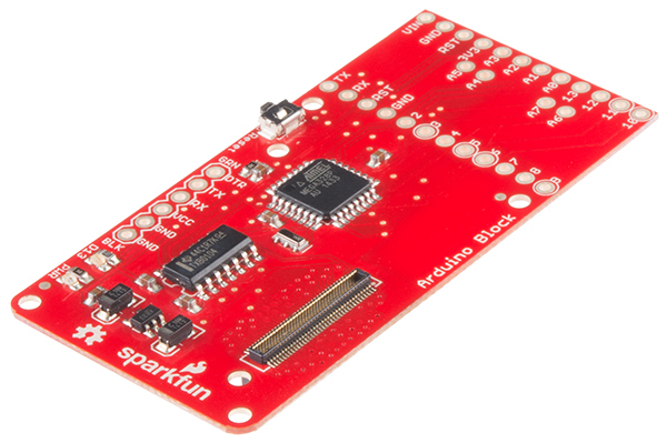
The Arduino Block for Edison provides the Intel(R) Edison with a direct, serial link to an Arduino-compatible ATmega328 microprocessor.
Why would you need an Arduino connected to your Edison? Isn't it powerful enough to handle anything that may be thrown at it? That's the problem -- it's almost too powerful. Because it's running an operating system, it's incapable of real-time processing -- the bread-and-butter of smaller microcontrollers like the ATmega328. Components which require precise timing -- like WS2812 LEDs or servo motors -- may be incompatible with the Edison as it can't reliably generate clock signals.
The Arduino block allows the Edison to offload those lower-level hardware tasks. Additional to that, if you've already written Arduino code for an external component, you don't have to port that code to the Edison -- just run it on an Arduino block!
Suggested Reading
If you are unfamiliar with Blocks, take a look at the General Guide to Sparkfun Blocks for Intel Edison.
Other tutorials that may help you on your Arduino Block adventure include:
Board Overview
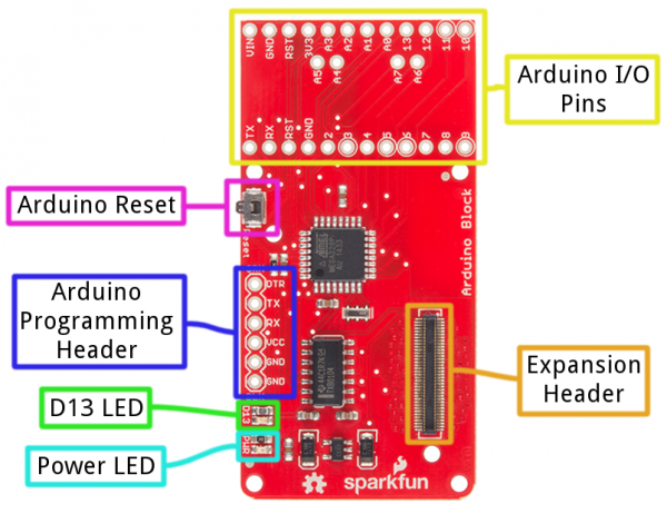
- Expansion Header -- The 70-pin Expansion header breaks out the functionality of the Intel Edison. This header also passes signals and power throughout the stack. These function much like an Arduino Shield.
- Arduino I/O Pins -- All of the Arduino's I/O pins are broken out to a pair of headers (plus a couple in between). This header footprint exactly matches that of the Arduino Pro Mini -- if you have any Mini shields they should mate exactly to this header.
- Arduino Programming Header -- The standard 6-pin FTDI header is used to program the Arduino's serial bootloader. Plug a 3.3V FTDI Basic in to program your Arduino.
- D13 LED -- Every good Arduino needs an LED! This small, green LED is tied to the Arduino's pin 13. Great for blinking "Hello, world" or debugging.
- Power LED -- The Arduino block has an on-board 3.3V regulator, and this LED is tied to the output of that regulator.
- Arduino Reset Button -- This reset button is tied to the Arduino's reset line. It will only reset the Arduino; it has no effect on the Edison.
Schematic Overview
The Arduino block pairs the ATmega328 to your Edison via one of two UARTs. The board defaults to connecting the Arduino to Edison via UART1. Jumpers (see more below) allow you to select UART2, if your application requires. Take care using UART2, though, it's default utility is for console access to the Edison.
The Arduino Block has an on-board 3.3V voltage regulator, which takes its input from the Edison's VSYS bus. Since the Arduino is running at 3.3V, its clock speed is limited to 8MHz.
If you want to take a closer look at the schematic, download the PDF here.
Jumpers
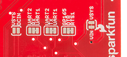
On the back-side of the Arduino block, there are a handful of jumpers, which lend extra utility to the board.
Three two-way jumpers -- for RX, TX, and DTR -- allow you to select between UART1 (default) and UART2. To switch these jumpers, grab a hobby knife, cut the default traces, and drop a solder blob between the middle pad and outer pad of your choice.
The jumper labeled VIN/VSYS allows you to remove the VSYS line from powering the Arduino block. This is handy if you need to isolate the Arduino block's power source from the Edison. In this case, you'll need to supply power (3.3-12V) externally via the "VIN" pin.
Using the Arduino Block
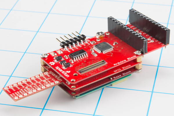
To use the Arduino Block, attach it to either an Edison or add it to a stack of other SparkFun Block's.
In order to supply power to your Edison, you'll need at least one additon Block in your stack. You can use a Base Block or Battery Block, for example.
Programming the Arduino
The Arduino on the Arduino Block can be programmed while it's either on or off the Edison. Depending on your application, though, it's recommended that you load code on the Arduino while it's disconnected from your Edison stack, before adding it to the rest of the system.
If you've ever uploaded an Arduino sketch to an Arduino Pro or Pro Mini, you're already familiar with uploading code to the Arduino block. Connect a 3.3V FTDI Basic to the 6-pin FTDI header on the board.
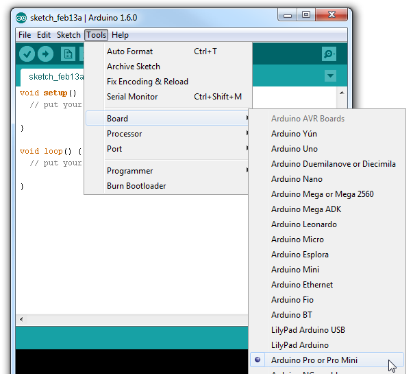
In Arduino (the non-Edison version of Arduino!), select "Arduino Pro or Pro Mini 3.3V/8MHz" from the Tools > Board menu. If you're using the latest release of Arduino (1.6 or later), first select Arduino Pro or Pro Mini from the "Board" menu.
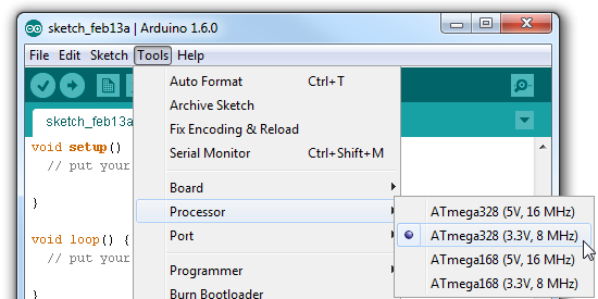
Then select ATmega328 (3.3V, 8MHz) from the "Processor" menu.
Then upload away!
Using the Arduino Pins
The Arduino's I/O pins are all broken out to a pair of headers. These headers match up exactly to the Arduino Pro Mini. If you have any shields or piggyback boards for a Pro Mini, it should work seamlessly with the Arduino Block.
You can solder headers, wires, or any other connectors to these pins.
If you're soldering headers to the pins, take extra care deciding which side to solder to. Depending on the rest of your Edison stackup, those headers might get in the way of connectors on other boards (the USB connectors on the Base and Console Blocks, in particular).
Connecting the Edison to the Arduino
The Arduino Block connects the Arduino to the Edison through a serial (UART) connection. Jumpers on the back of the board allow you select which of the Edison's two UARTs mate with the Arduino. Unless you can't avoid it, we recommend leaving the jumpers in the default configuration -- the Edison's UART2 is usually devoted to console access.
To program the Edison to control and interact with the Arduino, you'll need to use the UART to establish a communication protocol between the devices. See the next section for an easy example of UART communication between Arduino and Edison.
Controlling the Arduino Block with Firmata
Firmata is an established protocol popular within the Arduino realm for applications that require a separate machine (usually a computer) to control the Arduino. It's a serial-based protocol that uses defined messages to set digital pins, read analog pins, and do everything else you're used to with Arduino.
Firmata is so useful, the standard Arduino IDE even ships with the Firmata library. Here's an example of how an Edison can be used to control and interact with an Arduino running Firmata.
Upload StandardFirmata to the Arduino
Before uploading any code to the Edison, let's load something into the Arduino. Once the Firmata code is running on your Arduino, you may never have to upload code to it again.
Using the standard Arduino IDE (i.e. not the IDE built for Edison), load up the "StandardFirmata" sketch by going to File > Examples > Firmata > StandardFirmata.
language:c
    /*
 * Firmata is a generic protocol for communicating with microcontrollers
 * from software on a host computer. It is intended to work with
 * any host computer software package.
 *
 * To download a host software package, please clink on the following link
 * to open the download page in your default browser.
 *
 * http://firmata.org/wiki/Download
 */

/*
  Copyright (C) 2006-2008 Hans-Christoph Steiner.  All rights reserved.
  Copyright (C) 2010-2011 Paul Stoffregen.  All rights reserved.
  Copyright (C) 2009 Shigeru Kobayashi.  All rights reserved.
  Copyright (C) 2009-2011 Jeff Hoefs.  All rights reserved.

  This library is free software; you can redistribute it and/or
  modify it under the terms of the GNU Lesser General Public
  License as published by the Free Software Foundation; either
  version 2.1 of the License, or (at your option) any later version.

  See file LICENSE.txt for further informations on licensing terms.

  formatted using the GNU C formatting and indenting
*/

/*
 * TODO: use Program Control to load stored profiles from EEPROM
 */

#include <Servo.h>
#include <Wire.h>
#include <Firmata.h>

// move the following defines to Firmata.h?
#define I2C_WRITE B00000000
#define I2C_READ B00001000
#define I2C_READ_CONTINUOUSLY B00010000
#define I2C_STOP_READING B00011000
#define I2C_READ_WRITE_MODE_MASK B00011000
#define I2C_10BIT_ADDRESS_MODE_MASK B00100000

#define MAX_QUERIES 8
#define MINIMUM_SAMPLING_INTERVAL 10

#define REGISTER_NOT_SPECIFIED -1

/*==============================================================================
 * GLOBAL VARIABLES
 *============================================================================*/

/* analog inputs */
int analogInputsToReport = 0; // bitwise array to store pin reporting

/* digital input ports */
byte reportPINs[TOTAL_PORTS];       // 1 = report this port, 0 = silence
byte previousPINs[TOTAL_PORTS];     // previous 8 bits sent

/* pins configuration */
byte pinConfig[TOTAL_PINS];         // configuration of every pin
byte portConfigInputs[TOTAL_PORTS]; // each bit: 1 = pin in INPUT, 0 = anything else
int pinState[TOTAL_PINS];           // any value that has been written

/* timer variables */
unsigned long currentMillis;        // store the current value from millis()
unsigned long previousMillis;       // for comparison with currentMillis
int samplingInterval = 19;          // how often to run the main loop (in ms)

/* i2c data */
struct i2c_device_info {
  byte addr;
  byte reg;
  byte bytes;
};

/* for i2c read continuous more */
i2c_device_info query[MAX_QUERIES];

byte i2cRxData[32];
boolean isI2CEnabled = false;
signed char queryIndex = -1;
unsigned int i2cReadDelayTime = 0;  // default delay time between i2c read request and Wire.requestFrom()

Servo servos[MAX_SERVOS];
/*==============================================================================
 * FUNCTIONS
 *============================================================================*/

void readAndReportData(byte address, int theRegister, byte numBytes) {
  // allow I2C requests that don't require a register read
  // for example, some devices using an interrupt pin to signify new data available
  // do not always require the register read so upon interrupt you call Wire.requestFrom()
  if (theRegister != REGISTER_NOT_SPECIFIED) {
    Wire.beginTransmission(address);
    #if ARDUINO >= 100
    Wire.write((byte)theRegister);
    #else
    Wire.send((byte)theRegister);
    #endif
    Wire.endTransmission();
    delayMicroseconds(i2cReadDelayTime);  // delay is necessary for some devices such as WiiNunchuck
  } else {
    theRegister = 0;  // fill the register with a dummy value
  }

  Wire.requestFrom(address, numBytes);  // all bytes are returned in requestFrom

  // check to be sure correct number of bytes were returned by slave
  if(numBytes == Wire.available()) {
    i2cRxData[0] = address;
    i2cRxData[1] = theRegister;
    for (int i = 0; i < numBytes; i++) {
      #if ARDUINO >= 100
      i2cRxData[2 + i] = Wire.read();
      #else
      i2cRxData[2 + i] = Wire.receive();
      #endif
    }
  }
  else {
    if(numBytes > Wire.available()) {
      Firmata.sendString("I2C Read Error: Too many bytes received");
    } else {
      Firmata.sendString("I2C Read Error: Too few bytes received");
    }
  }

  // send slave address, register and received bytes
  Firmata.sendSysex(SYSEX_I2C_REPLY, numBytes + 2, i2cRxData);
}

void outputPort(byte portNumber, byte portValue, byte forceSend)
{
  // pins not configured as INPUT are cleared to zeros
  portValue = portValue & portConfigInputs[portNumber];
  // only send if the value is different than previously sent
  if(forceSend || previousPINs[portNumber] != portValue) {
    Firmata.sendDigitalPort(portNumber, portValue);
    previousPINs[portNumber] = portValue;
  }
}

/* -----------------------------------------------------------------------------
 * check all the active digital inputs for change of state, then add any events
 * to the Serial output queue using Serial.print() */
void checkDigitalInputs(void)
{
  /* Using non-looping code allows constants to be given to readPort().
   * The compiler will apply substantial optimizations if the inputs
   * to readPort() are compile-time constants. */
  if (TOTAL_PORTS > 0 && reportPINs[0]) outputPort(0, readPort(0, portConfigInputs[0]), false);
  if (TOTAL_PORTS > 1 && reportPINs[1]) outputPort(1, readPort(1, portConfigInputs[1]), false);
  if (TOTAL_PORTS > 2 && reportPINs[2]) outputPort(2, readPort(2, portConfigInputs[2]), false);
  if (TOTAL_PORTS > 3 && reportPINs[3]) outputPort(3, readPort(3, portConfigInputs[3]), false);
  if (TOTAL_PORTS > 4 && reportPINs[4]) outputPort(4, readPort(4, portConfigInputs[4]), false);
  if (TOTAL_PORTS > 5 && reportPINs[5]) outputPort(5, readPort(5, portConfigInputs[5]), false);
  if (TOTAL_PORTS > 6 && reportPINs[6]) outputPort(6, readPort(6, portConfigInputs[6]), false);
  if (TOTAL_PORTS > 7 && reportPINs[7]) outputPort(7, readPort(7, portConfigInputs[7]), false);
  if (TOTAL_PORTS > 8 && reportPINs[8]) outputPort(8, readPort(8, portConfigInputs[8]), false);
  if (TOTAL_PORTS > 9 && reportPINs[9]) outputPort(9, readPort(9, portConfigInputs[9]), false);
  if (TOTAL_PORTS > 10 && reportPINs[10]) outputPort(10, readPort(10, portConfigInputs[10]), false);
  if (TOTAL_PORTS > 11 && reportPINs[11]) outputPort(11, readPort(11, portConfigInputs[11]), false);
  if (TOTAL_PORTS > 12 && reportPINs[12]) outputPort(12, readPort(12, portConfigInputs[12]), false);
  if (TOTAL_PORTS > 13 && reportPINs[13]) outputPort(13, readPort(13, portConfigInputs[13]), false);
  if (TOTAL_PORTS > 14 && reportPINs[14]) outputPort(14, readPort(14, portConfigInputs[14]), false);
  if (TOTAL_PORTS > 15 && reportPINs[15]) outputPort(15, readPort(15, portConfigInputs[15]), false);
}

// -----------------------------------------------------------------------------
/* sets the pin mode to the correct state and sets the relevant bits in the
 * two bit-arrays that track Digital I/O and PWM status
 */
void setPinModeCallback(byte pin, int mode)
{
  if (pinConfig[pin] == I2C && isI2CEnabled && mode != I2C) {
    // disable i2c so pins can be used for other functions
    // the following if statements should reconfigure the pins properly
    disableI2CPins();
  }
  if (IS_PIN_SERVO(pin) && mode != SERVO && servos[PIN_TO_SERVO(pin)].attached()) {
    servos[PIN_TO_SERVO(pin)].detach();
  }
  if (IS_PIN_ANALOG(pin)) {
    reportAnalogCallback(PIN_TO_ANALOG(pin), mode == ANALOG ? 1 : 0); // turn on/off reporting
  }
  if (IS_PIN_DIGITAL(pin)) {
    if (mode == INPUT) {
      portConfigInputs[pin/8] |= (1 << (pin & 7));
    } else {
      portConfigInputs[pin/8] &= ~(1 << (pin & 7));
    }
  }
  pinState[pin] = 0;
  switch(mode) {
  case ANALOG:
    if (IS_PIN_ANALOG(pin)) {
      if (IS_PIN_DIGITAL(pin)) {
        pinMode(PIN_TO_DIGITAL(pin), INPUT); // disable output driver
        digitalWrite(PIN_TO_DIGITAL(pin), LOW); // disable internal pull-ups
      }
      pinConfig[pin] = ANALOG;
    }
    break;
  case INPUT:
    if (IS_PIN_DIGITAL(pin)) {
      pinMode(PIN_TO_DIGITAL(pin), INPUT); // disable output driver
      digitalWrite(PIN_TO_DIGITAL(pin), LOW); // disable internal pull-ups
      pinConfig[pin] = INPUT;
    }
    break;
  case OUTPUT:
    if (IS_PIN_DIGITAL(pin)) {
      digitalWrite(PIN_TO_DIGITAL(pin), LOW); // disable PWM
      pinMode(PIN_TO_DIGITAL(pin), OUTPUT);
      pinConfig[pin] = OUTPUT;
    }
    break;
  case PWM:
    if (IS_PIN_PWM(pin)) {
      pinMode(PIN_TO_PWM(pin), OUTPUT);
      analogWrite(PIN_TO_PWM(pin), 0);
      pinConfig[pin] = PWM;
    }
    break;
  case SERVO:
    if (IS_PIN_SERVO(pin)) {
      pinConfig[pin] = SERVO;
      if (!servos[PIN_TO_SERVO(pin)].attached()) {
          servos[PIN_TO_SERVO(pin)].attach(PIN_TO_DIGITAL(pin));
      }
    }
    break;
  case I2C:
    if (IS_PIN_I2C(pin)) {
      // mark the pin as i2c
      // the user must call I2C_CONFIG to enable I2C for a device
      pinConfig[pin] = I2C;
    }
    break;
  default:
    Firmata.sendString("Unknown pin mode"); // TODO: put error msgs in EEPROM
  }
  // TODO: save status to EEPROM here, if changed
}

void analogWriteCallback(byte pin, int value)
{
  if (pin < TOTAL_PINS) {
    switch(pinConfig[pin]) {
    case SERVO:
      if (IS_PIN_SERVO(pin))
        servos[PIN_TO_SERVO(pin)].write(value);
        pinState[pin] = value;
      break;
    case PWM:
      if (IS_PIN_PWM(pin))
        analogWrite(PIN_TO_PWM(pin), value);
        pinState[pin] = value;
      break;
    }
  }
}

void digitalWriteCallback(byte port, int value)
{
  byte pin, lastPin, mask=1, pinWriteMask=0;

  if (port < TOTAL_PORTS) {
    // create a mask of the pins on this port that are writable.
    lastPin = port*8+8;
    if (lastPin > TOTAL_PINS) lastPin = TOTAL_PINS;
    for (pin=port*8; pin < lastPin; pin++) {
      // do not disturb non-digital pins (eg, Rx & Tx)
      if (IS_PIN_DIGITAL(pin)) {
        // only write to OUTPUT and INPUT (enables pullup)
        // do not touch pins in PWM, ANALOG, SERVO or other modes
        if (pinConfig[pin] == OUTPUT || pinConfig[pin] == INPUT) {
          pinWriteMask |= mask;
          pinState[pin] = ((byte)value & mask) ? 1 : 0;
        }
      }
      mask = mask << 1;
    }
    writePort(port, (byte)value, pinWriteMask);
  }
}


// -----------------------------------------------------------------------------
/* sets bits in a bit array (int) to toggle the reporting of the analogIns
 */
//void FirmataClass::setAnalogPinReporting(byte pin, byte state) {
//}
void reportAnalogCallback(byte analogPin, int value)
{
  if (analogPin < TOTAL_ANALOG_PINS) {
    if(value == 0) {
      analogInputsToReport = analogInputsToReport &~ (1 << analogPin);
    } else {
      analogInputsToReport = analogInputsToReport | (1 << analogPin);
    }
  }
  // TODO: save status to EEPROM here, if changed
}

void reportDigitalCallback(byte port, int value)
{
  if (port < TOTAL_PORTS) {
    reportPINs[port] = (byte)value;
  }
  // do not disable analog reporting on these 8 pins, to allow some
  // pins used for digital, others analog.  Instead, allow both types
  // of reporting to be enabled, but check if the pin is configured
  // as analog when sampling the analog inputs.  Likewise, while
  // scanning digital pins, portConfigInputs will mask off values from any
  // pins configured as analog
}

/*==============================================================================
 * SYSEX-BASED commands
 *============================================================================*/

void sysexCallback(byte command, byte argc, byte *argv)
{
  byte mode;
  byte slaveAddress;
  byte slaveRegister;
  byte data;
  unsigned int delayTime;

  switch(command) {
  case I2C_REQUEST:
    mode = argv[1] & I2C_READ_WRITE_MODE_MASK;
    if (argv[1] & I2C_10BIT_ADDRESS_MODE_MASK) {
      Firmata.sendString("10-bit addressing mode is not yet supported");
      return;
    }
    else {
      slaveAddress = argv[0];
    }

    switch(mode) {
    case I2C_WRITE:
      Wire.beginTransmission(slaveAddress);
      for (byte i = 2; i < argc; i += 2) {
        data = argv[i] + (argv[i + 1] << 7);
        #if ARDUINO >= 100
        Wire.write(data);
        #else
        Wire.send(data);
        #endif
      }
      Wire.endTransmission();
      delayMicroseconds(70);
      break;
    case I2C_READ:
      if (argc == 6) {
        // a slave register is specified
        slaveRegister = argv[2] + (argv[3] << 7);
        data = argv[4] + (argv[5] << 7);  // bytes to read
        readAndReportData(slaveAddress, (int)slaveRegister, data);
      }
      else {
        // a slave register is NOT specified
        data = argv[2] + (argv[3] << 7);  // bytes to read
        readAndReportData(slaveAddress, (int)REGISTER_NOT_SPECIFIED, data);
      }
      break;
    case I2C_READ_CONTINUOUSLY:
      if ((queryIndex + 1) >= MAX_QUERIES) {
        // too many queries, just ignore
        Firmata.sendString("too many queries");
        break;
      }
      queryIndex++;
      query[queryIndex].addr = slaveAddress;
      query[queryIndex].reg = argv[2] + (argv[3] << 7);
      query[queryIndex].bytes = argv[4] + (argv[5] << 7);
      break;
    case I2C_STOP_READING:
      byte queryIndexToSkip;
      // if read continuous mode is enabled for only 1 i2c device, disable
      // read continuous reporting for that device
      if (queryIndex <= 0) {
        queryIndex = -1;
      } else {
        // if read continuous mode is enabled for multiple devices,
        // determine which device to stop reading and remove it's data from
        // the array, shifiting other array data to fill the space
        for (byte i = 0; i < queryIndex + 1; i++) {
          if (query[i].addr = slaveAddress) {
            queryIndexToSkip = i;
            break;
          }
        }

        for (byte i = queryIndexToSkip; i<queryIndex + 1; i++) {
          if (i < MAX_QUERIES) {
            query[i].addr = query[i+1].addr;
            query[i].reg = query[i+1].addr;
            query[i].bytes = query[i+1].bytes;
          }
        }
        queryIndex--;
      }
      break;
    default:
      break;
    }
    break;
  case I2C_CONFIG:
    delayTime = (argv[0] + (argv[1] << 7));

    if(delayTime > 0) {
      i2cReadDelayTime = delayTime;
    }

    if (!isI2CEnabled) {
      enableI2CPins();
    }

    break;
  case SERVO_CONFIG:
    if(argc > 4) {
      // these vars are here for clarity, they'll optimized away by the compiler
      byte pin = argv[0];
      int minPulse = argv[1] + (argv[2] << 7);
      int maxPulse = argv[3] + (argv[4] << 7);

      if (IS_PIN_SERVO(pin)) {
        if (servos[PIN_TO_SERVO(pin)].attached())
          servos[PIN_TO_SERVO(pin)].detach();
        servos[PIN_TO_SERVO(pin)].attach(PIN_TO_DIGITAL(pin), minPulse, maxPulse);
        setPinModeCallback(pin, SERVO);
      }
    }
    break;
  case SAMPLING_INTERVAL:
    if (argc > 1) {
      samplingInterval = argv[0] + (argv[1] << 7);
      if (samplingInterval < MINIMUM_SAMPLING_INTERVAL) {
        samplingInterval = MINIMUM_SAMPLING_INTERVAL;
      }
    } else {
      //Firmata.sendString("Not enough data");
    }
    break;
  case EXTENDED_ANALOG:
    if (argc > 1) {
      int val = argv[1];
      if (argc > 2) val |= (argv[2] << 7);
      if (argc > 3) val |= (argv[3] << 14);
      analogWriteCallback(argv[0], val);
    }
    break;
  case CAPABILITY_QUERY:
    Serial.write(START_SYSEX);
    Serial.write(CAPABILITY_RESPONSE);
    for (byte pin=0; pin < TOTAL_PINS; pin++) {
      if (IS_PIN_DIGITAL(pin)) {
        Serial.write((byte)INPUT);
        Serial.write(1);
        Serial.write((byte)OUTPUT);
        Serial.write(1);
      }
      if (IS_PIN_ANALOG(pin)) {
        Serial.write(ANALOG);
        Serial.write(10);
      }
      if (IS_PIN_PWM(pin)) {
        Serial.write(PWM);
        Serial.write(8);
      }
      if (IS_PIN_SERVO(pin)) {
        Serial.write(SERVO);
        Serial.write(14);
      }
      if (IS_PIN_I2C(pin)) {
        Serial.write(I2C);
        Serial.write(1);  // to do: determine appropriate value
      }
      Serial.write(127);
    }
    Serial.write(END_SYSEX);
    break;
  case PIN_STATE_QUERY:
    if (argc > 0) {
      byte pin=argv[0];
      Serial.write(START_SYSEX);
      Serial.write(PIN_STATE_RESPONSE);
      Serial.write(pin);
      if (pin < TOTAL_PINS) {
        Serial.write((byte)pinConfig[pin]);
    Serial.write((byte)pinState[pin] & 0x7F);
    if (pinState[pin] & 0xFF80) Serial.write((byte)(pinState[pin] >> 7) & 0x7F);
    if (pinState[pin] & 0xC000) Serial.write((byte)(pinState[pin] >> 14) & 0x7F);
      }
      Serial.write(END_SYSEX);
    }
    break;
  case ANALOG_MAPPING_QUERY:
    Serial.write(START_SYSEX);
    Serial.write(ANALOG_MAPPING_RESPONSE);
    for (byte pin=0; pin < TOTAL_PINS; pin++) {
      Serial.write(IS_PIN_ANALOG(pin) ? PIN_TO_ANALOG(pin) : 127);
    }
    Serial.write(END_SYSEX);
    break;
  }
}

void enableI2CPins()
{
  byte i;
  // is there a faster way to do this? would probaby require importing
  // Arduino.h to get SCL and SDA pins
  for (i=0; i < TOTAL_PINS; i++) {
    if(IS_PIN_I2C(i)) {
      // mark pins as i2c so they are ignore in non i2c data requests
      setPinModeCallback(i, I2C);
    }
  }

  isI2CEnabled = true;

  // is there enough time before the first I2C request to call this here?
  Wire.begin();
}

/* disable the i2c pins so they can be used for other functions */
void disableI2CPins() {
    isI2CEnabled = false;
    // disable read continuous mode for all devices
    queryIndex = -1;
    // uncomment the following if or when the end() method is added to Wire library
    // Wire.end();
}

/*==============================================================================
 * SETUP()
 *============================================================================*/

void systemResetCallback()
{
  // initialize a defalt state
  // TODO: option to load config from EEPROM instead of default
  if (isI2CEnabled) {
    disableI2CPins();
  }
  for (byte i=0; i < TOTAL_PORTS; i++) {
    reportPINs[i] = false;      // by default, reporting off
    portConfigInputs[i] = 0;    // until activated
    previousPINs[i] = 0;
  }
  // pins with analog capability default to analog input
  // otherwise, pins default to digital output
  for (byte i=0; i < TOTAL_PINS; i++) {
    if (IS_PIN_ANALOG(i)) {
      // turns off pullup, configures everything
      setPinModeCallback(i, ANALOG);
    } else {
      // sets the output to 0, configures portConfigInputs
      setPinModeCallback(i, OUTPUT);
    }
  }
  // by default, do not report any analog inputs
  analogInputsToReport = 0;

  /* send digital inputs to set the initial state on the host computer,
   * since once in the loop(), this firmware will only send on change */
  /*
  TODO: this can never execute, since no pins default to digital input
        but it will be needed when/if we support EEPROM stored config
  for (byte i=0; i < TOTAL_PORTS; i++) {
    outputPort(i, readPort(i, portConfigInputs[i]), true);
  }
  */
}

void setup()
{
  Firmata.setFirmwareVersion(FIRMATA_MAJOR_VERSION, FIRMATA_MINOR_VERSION);

  Firmata.attach(ANALOG_MESSAGE, analogWriteCallback);
  Firmata.attach(DIGITAL_MESSAGE, digitalWriteCallback);
  Firmata.attach(REPORT_ANALOG, reportAnalogCallback);
  Firmata.attach(REPORT_DIGITAL, reportDigitalCallback);
  Firmata.attach(SET_PIN_MODE, setPinModeCallback);
  Firmata.attach(START_SYSEX, sysexCallback);
  Firmata.attach(SYSTEM_RESET, systemResetCallback);

  Firmata.begin(57600);
  systemResetCallback();  // reset to default config
}

/*==============================================================================
 * LOOP()
 *============================================================================*/
void loop()
{
  byte pin, analogPin;

  /* DIGITALREAD - as fast as possible, check for changes and output them to the
   * FTDI buffer using Serial.print()  */
  checkDigitalInputs();

  /* SERIALREAD - processing incoming messagse as soon as possible, while still
   * checking digital inputs.  */
  while(Firmata.available())
    Firmata.processInput();

  /* SEND FTDI WRITE BUFFER - make sure that the FTDI buffer doesn't go over
   * 60 bytes. use a timer to sending an event character every 4 ms to
   * trigger the buffer to dump. */

  currentMillis = millis();
  if (currentMillis - previousMillis > samplingInterval) {
    previousMillis += samplingInterval;
    /* ANALOGREAD - do all analogReads() at the configured sampling interval */
    for(pin=0; pin<TOTAL_PINS; pin++) {
      if (IS_PIN_ANALOG(pin) && pinConfig[pin] == ANALOG) {
        analogPin = PIN_TO_ANALOG(pin);
        if (analogInputsToReport & (1 << analogPin)) {
          Firmata.sendAnalog(analogPin, analogRead(analogPin));
        }
      }
    }
    // report i2c data for all device with read continuous mode enabled
    if (queryIndex > -1) {
      for (byte i = 0; i < queryIndex + 1; i++) {
        readAndReportData(query[i].addr, query[i].reg, query[i].bytes);
      }
    }
  }
}
With the Firmata firmware uploaded, you can disconnect the FTDI Basic, and connect the Arduino Block to your Edison stack.
Edison Firmata for Arduino Client
The harder part of this equation is writing something that executes on the Edison which interacts with our Firmata-running Arduino. There are tons of great client examples in the Firmata GitHub profile, but nothing quite built for the Edison.
Riffing on the Firmata Processing example, we wrote this sketch to enact an Edison Firmata client.
Here's the sketch. Copy/paste from below, or grab the latest version from this Gist:
language:c
/****************************************************************
   Edison Firmata Client
   by: Jim Lindblom @ SparkFun Electronics
   created on: Februrary 12, 2015
   github:

   This is an Firmata client sketch for the Edison. It can
   communicate with an Arduino running Firmata over a Serial
   connection.

   Support for the following functions is written:
     firmata_init() -- set up firmata and pin reporting
     firmata_pinMode([pin], [0, 1, 2, 3, 4, 5, 6])
     firmata_digitalWrite([pin], [LOW/HIGH])
     firmata_analogWrite([pin], [0-255])
     firmata_analogRead([0-7])
     firmata_digitalRead([pin])
     firmata_servoWrite([pin], [value])

   Development Environment Specifics:
   Arduino 1.5.3 (for Edison)
   Intel Edison rev C
   Arduino Block for Edison
     Arduino should be running StandardFirmata

   This sketch is based on Firmata's processing client:
   https://github.com/firmata/processing
   As such, it is released under the same, free license. You can
   redistribute it and/or modify it under the terms of the GNU
   Lesser General Public License as published by the Free
   Software Foundation; either version 2.1 of the License, or
   (at your option) any later version.

   Distributed as-is; no warranty is given.
****************************************************************/
// SerialEvent1 isn't defined in the Edison core (I think).
// To get some form of interrupt-driven Serial input, we'll read
// serial in on a timer.
#include <TimerOne.h>

#define MAX_DATA_BYTES 4096
#define MAX_PINS 128

// Pin Mode definitons:
// Use any of these six values to set a pin to INPUT, OUTPUT,
// ANALOG, PWM, SERVO, SHIFT, or I2C.
enum const_pin_mode {
  MODE_INPUT,  // 0
  MODE_OUTPUT, // 1
  MODE_ANALOG, // 2
  MODE_PWM,    // 3
  MODE_SERVO,  // 4
  MODE_SHIFT,  // 5
  MODE_I2C     // 6
};

// Message Types
// Used by the low-level Firmata functions to set up the
// Firmata messages.
#define ANALOG_MESSAGE  0xE0
#define DIGITAL_MESSAGE 0x90
#define REPORT_ANALOG   0xC0
#define REPORT_DIGITAL  0xD0
#define START_SYSEX     0xF0
#define SET_PIN_MODE    0xF4
#define END_SYSEX       0xF7
#define REPORT_VERSION  0xF9
#define SYSTEM_RESET    0xFF

// Extended Commands:
// Used by the low-level Firmata functions to set up the
// Firmata messages.
#define SERVO_CONFIG            0x70
#define STRING_DATA             0x71
#define SHIFT_DATA              0x75
#define I2C_REQUEST             0x76
#define I2C_REPLY               0x77
#define I2C_CONFIG              0x78
#define EXTENDED_ANALOG         0x6F
#define PIN_STATE_QUERY         0x6D
#define PIN_STATE_RESPONSE      0x6E
#define CAPABILITY_QUERY        0x6B
#define CAPABILITY_RESPONSE     0x6C
#define ANALOG_MAPPING_QUERY    0x69
#define ANALOG_MAPPING_RESPONSE 0x6A
#define REPORT_FIRMWARE         0x79
#define SAMPLING_INTERVAL       0x7A
#define SYSEX_NON_REALTIME      0x7E
#define SYSEX_REALTIME          0x7F

// Flags and variables to keep track of message reading status:
boolean parsingSysex = false;
int waitForData = 0;
int storedInputData[MAX_DATA_BYTES];
int sysexBytesRead = 0;
int executeMultiByteCommand = 0;
int multiByteChannel = 0;
// Variable arrays to keep track of pin values read in.
int digitalInputData[] = {0, 0, 0, 0, 0, 0, 0, 0,
                          0, 0, 0, 0, 0, 0, 0, 0};
int analogInputData[] = {0, 0, 0, 0, 0, 0, 0, 0,
                         0, 0, 0, 0, 0, 0, 0, 0};
int analogChannel[MAX_PINS];
boolean blinkFlag = false;

void setup()
{
  // Debug messages are sent out Serial. Use the Serial monitor
  // at 9600 bps to read pin values.
  Serial.begin(9600);

  // firmata_init sets up our firmata client. It tells the
  // Firmata device to begin streaming analog values and any
  // digital pin value changes.
  firmata_init();

  // Use firmata_pinMode([pin], [value]) to set up pins on the
  // Firmata host:
  firmata_pinMode(13, MODE_OUTPUT); // LED tied to pin 13
  firmata_pinMode(4, MODE_INPUT);   // Digital input on pin 4
  firmata_pinMode(A0, MODE_ANALOG); // Analog input on pin 0
  firmata_pinMode(3, MODE_PWM);     // PWM LED on pin 3
}

void loop()
{
  // Print the value of our Firmata Arduino's A0 pin:
  int a0Value = firmata_analogRead(0);
  Serial.print("A0: ");
  Serial.println(a0Value);


  // Print the value of our digital input on pin 4:
  int d4Value = firmata_digitalRead(4);
  Serial.print("Pin 4: ");
  Serial.println(d4Value);

  if (d4Value == LOW)
  {
    // Scale the value of A0 to write a PWM output on pin 3:
    firmata_analogWrite(3, firmata_analogRead(0) / 4);
  }
  else
  {
    // Scale the value of A0 to write a PWM output on pin 3:
    firmata_analogWrite(3, 0);
  }

}

///////////////////////////////////
// Upper Level Firmata Functions //
///////////////////////////////////
// Firmata functions that you should use in your sketch above.
// If this was a class, these'd be public functions.

// firmata_init() --
// - Initialize our Firmata Serial port.
// - Set up a timer to read in Serial messages outside of loop().
// - Configure our Firmata Arduino to report all digital outputs
// - Configure our Firmata Arduino to report all analog outputs
void firmata_init()
{
  Serial1.begin(57600);
  // set a timer of length 100,000 microseconds ( 0.1 sec - or 10Hz)
  Timer1.initialize(1000);
  Timer1.attachInterrupt( checkSerial ); // attach the service routine here

  // Turn on reporting for all digital ports
  for (int i=0; i<16; i++)
  {
    Serial1.write(REPORT_DIGITAL | i);
    Serial1.write(1);
  }
  // This function will check for analog channels and set them
  // to REPORTING
  firmata_queryAnalogMapping();
}

// firmata_digitalRead([pin]) --
// - Returns the latest digital input value we've read on the
//   requested pin.
// - digitalInputData[] is updated in firmata_processInput()
//   as serial messages come in.
int firmata_digitalRead(int pin)
{
  return (digitalInputData[pin >> 3] >> (pin & 0x07)) & 0x01;
}

// firmata_analogRead([pin])
// - Returns the latest analog value we've read on the requested
//   pin.
// - analogInputData[] is updated in firmata_processInput()
//   as serial messages come in.
int firmata_analogRead(int pin)
{
  return analogInputData[pin];
}

// firmata_pinMode([pin], [mode])
// - Set an Arduino pin to input, output, analog in, PWM, servo,
//   shift register, or i2c.
// - [pin] - can be any Arduino pin 0-13, A0-A7
// - [mode] - should be one of these defined values:
//          - MODE_INPUT  - Digital input
//          - MODE_OUTPUT - Digital output
//          - MODE_ANALOG - Analog input
//          - MODE_PWM    - Analog output
//          - MODE_SERVO  - Servo output
//          - MODE_SHIFT  - Shift register output
void firmata_pinMode(int pin, int mode)
{
  Serial1.write(SET_PIN_MODE);
  Serial1.write(pin);
  Serial1.write(mode);
}

// firmata_digitalWrite([pin], [value])
// - Set an Arduino digital pin to HIGH or LOW
// - [pin] - Any digital pin 0-18
// - [value] - LOW or HIGH
void firmata_digitalWrite(int pin, int value)
{
  int port = (pin >> 3) & 0x0F;
  int data;

  if (value)
    data |= (1 << (pin & 0x07));
  else
    data &= ~(1 << (pin & 0x07));

  Serial1.write(DIGITAL_MESSAGE | port); // Digital data
  Serial1.write(data & 0x7F); // Digital pins 0-6 bitmask
  Serial1.write(data >> 7);   // Digital pin 7 bitmask
}

// firmata_analogWrite([pin], [value])
// - Set an Arduino pin - CONFIGURED AS PWM (!) - to an
//   analog output value.
// - [pin] - Any analog output capable pin (3, 5, 6, 9, 10, 11
// - [value] - 0-255
void firmata_analogWrite(int pin, int value)
{

  Serial1.write(ANALOG_MESSAGE | (pin& 0x0F)); // Analog pin
  Serial1.write(value & 0x7F); // Analog LS 7 bits
  Serial1.write(value >> 7);   // Analog MS 7 bits
}

// firmata_servoWrite([pin], [value])
// - Set an Arduino pin - CONFIGURED AS SERVO (!) - to output
//   a servo signal.
void firmata_servoWrite(int pin, int value)
{
  Serial1.write(ANALOG_MESSAGE | (pin & 0x0F));
  Serial1.write(value & 0x7F);
  Serial1.write(value >> 7);
}

/////////////////////////////////
// Low level Firmata functions //
/////////////////////////////////
// Firmata helper functions you probably won't need to call in
// your sketch. If this was a class, these'd be private functions.

// checkSerial()
// Interrupt-recurring function. Checks for available serial data
// and processes any serial messages that come in.
void checkSerial()
{
  while (Serial1.available())
  {
    //Serial.write(Serial1.read());
    firmata_processInput((unsigned char) Serial1.read());
  }
  if (blinkFlag)
  {
    firmata_digitalWrite(13, HIGH); // Tell Arduino to write 13 HIGH
    blinkFlag = false;
  }
  else
  {
    firmata_digitalWrite(13, LOW); // Tell Arduino to write 13 HIGH
    blinkFlag = true;
  }
}

// firmata_processInput([inputData])
// Handles all Firmata messages - everything from version checks
// to analog and digital readings.
void firmata_processInput(unsigned char inputData)
{
  int command;

  if (parsingSysex) // If we're parsing a system message
  {
    if (inputData == END_SYSEX)
    { // Received end of system message, process it
      parsingSysex = false;
      firmata_processSysexMessage();
    }
    else
    { // In the system message, add to it
      storedInputData[sysexBytesRead] = inputData;
      sysexBytesRead++;
    }
  }
  else if (waitForData > 0 && inputData < 128)
  { // Else waiting for data
    waitForData--; // Decrement wait for data
    storedInputData[waitForData] = inputData;

    if (executeMultiByteCommand != 0 && waitForData == 0)
    {
      switch(executeMultiByteCommand)
      {
      case DIGITAL_MESSAGE:
        firmata_setDigitalInputs(multiByteChannel,
                 (storedInputData[0] << 7) + storedInputData[1]);
        break;
      case ANALOG_MESSAGE:
        firmata_setAnalogInput(multiByteChannel,
                 (storedInputData[0] << 7) + storedInputData[1]);
        break;
      case REPORT_VERSION:
        firmata_setVersion(storedInputData[1], storedInputData[0]);
        break;
      }
    }
  }
  else // Beginning of a message
  {
    if (inputData < 0xF0)
    {
      command = inputData & 0xF0;
      multiByteChannel = inputData & 0x0F;
    }
    else
    {
      command = inputData;
    }
    switch (command)
    {
    case DIGITAL_MESSAGE:
    case ANALOG_MESSAGE:
    case REPORT_VERSION:
      waitForData = 2;
      executeMultiByteCommand = command;
      break;
    case START_SYSEX:
      parsingSysex = true;
      sysexBytesRead = 0;
      break;
    }
  }
}

// firmata_processSysexMessage()
// - Process a system message.
// - Mostly just handles defining which pins are analog channels.
void firmata_processSysexMessage()
{
  switch (storedInputData[0])
  {
  case ANALOG_MAPPING_RESPONSE:
    // Begin by setting every channel to NOT analog (127)
    for (int pin = 0; pin < sizeof(analogChannel); pin++)
      analogChannel[pin] = 127;
    // Enumerate analog channels:
    for (int i = 1; i < sysexBytesRead; i++)
      analogChannel[i - 1] = storedInputData[i];
    // Set each analog output to reporting
    for (int pin = 0; pin < sizeof(analogChannel); pin++)
    {
      if (analogChannel[pin] != 127)
      {
        Serial1.write(REPORT_ANALOG | analogChannel[pin]);
        Serial1.write(1);
      }
    }
    break;
  }
}

// firmata_queryAnalogMapping()
// - Send the ANALOG_MAPPING_QUERY request message.
// - Called in init to keep track of which pins are analog ins
void firmata_queryAnalogMapping()
{
  Serial1.write(START_SYSEX);
  Serial1.write(ANALOG_MAPPING_QUERY);
  Serial1.write(END_SYSEX);
}

// firmata_setDigitalInputs()
// - Set a value in the digitalInputData array to portData
void firmata_setDigitalInputs(int portNumber, int portData)
{
  digitalInputData[portNumber] = portData;
}

// firmata_setAnalogInput
// - Set an analog pin value to [value].
void firmata_setAnalogInput(int pin, int value)
{
  analogInputData[pin] = value;
}

void firmata_setVersion(int majorVersion, int minorVersion)
{
  //! Todo
}
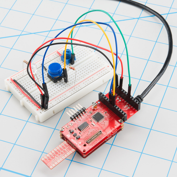
After uploading that sketch to your Edison, your Arduino Block should begin blinking the D13 pin. You can also open up the Serial Monitor to see what values your Arduino Block is reading in on D4 and A0.
This serves as a simple Firmata client for the Edison, but it should be easily expandable. Try using any of these functions (defined in lower portions of the sketch) to add more features to your Edison Firmata Client:
firmata_pinMode([pin], [mode])-- As with any Arduino sketch, setting the pin's mode is critical. Firmata requires an extra bit of information. Use any Arduino pin for the[pin]variable. For the[mode]variable use eitherMODE_INPUT,MODE_OUTPUT,MODE_ANALOG,MODE_PWM,MODE_SERVO, orMODE_SHIFT.firmata_digitalRead([pin])-- Read in the digital value of a pin. This function will return a value between 0 and 1. That pin should be set asMODE_INPUTbefore calling this function.firmata_analogRead([pin])-- Read in the value of an anlog pin. This function will return a value between 0 and 1023. The pins should be set asMODE_ANALOGbefore being read.firmata_digitalWrite([pin], [value])-- Write a digital pin either HIGH or LOW. The pin should be set asMODE_OUTPUTbefore calling the function.firmata_analogWrite([pin], [value])-- Write an analog-output pin to a value between 0 and 255. The pin must be PWM-capable -- that means either pin 3, 5, 6, 9, 10, or 11. And it should be configured as aMODE_PWMbefore hand.firmata_servoWrite([pin], [value])--Set a pin to output a servo signal. The value here is an angle between 0 and whatever the high-end angle of your servo is. Remember to set the pin toMODE_SERVObefore calling this function!
Don't feel like you have to user Firmata when using the Arduino block with your Edison. It's a great place to start, though, if you're looking for a simple communication protocol over the serial interface.
Resources and Going Further
Now that you have had a brief overview of the Arduino Block, take a look at some of these other tutorials. These tutorials cover programming, Block stacking, and interfacing with the Intel Edison ecosystems.
Edison General Topics:
- General Guide to Sparkfun Blocks for Intel Edison
- Edison Getting Started Guide
- Loading Debian (Ubilinix) on the Edison
Check out these other Edison related tutorials from SparkFun:
