SparkFun Blocks for Intel® Edison - ADC V20
 SFUptownMaker,
  HelloTechie,
  CaseyTheRobot
Board Overview
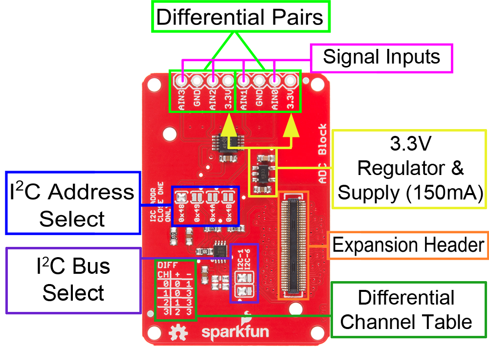
Signal Inputs - Four single inputs are available. The reference voltage for each is produced internal to the ADC under software control; do not exceed 3.3V input to these pins!
Differential Channel Setting Table - Use two inputs to create a differential pair. Useful for eliminating noise in some sensors or measuring very small signals. This table shows the channel options for the "getDiffResult(channel)" function.
I2C Address Select - Apply solder to only one of the four jumpers to select the address. Do not short two of these at once. Bad stuff will happen.
I2C Bus Select - Change both of these jumpers to select between routing the I2C signals to bus 6 or bus 1. Bus 1 is the default (and preferred) channel, as it has no other system devices on it. Bus 6 is shared with some internal devices, but if you wish to use this block with the Arduino IDE, you'll want to change these jumpers so the solder blobs connect the bottom pad with the center pad.
3.3V 150mA Supply - This supply provides an on-board reference for the ADC, and can power small sensors (for example, potentiometers or temperature sensors).