SparkFun Blocks for Intel® Edison - 9 Degrees of Freedom Block
 Shawn Hymel,
  CaseyTheRobot,
  SFUptownMaker
Board Overview
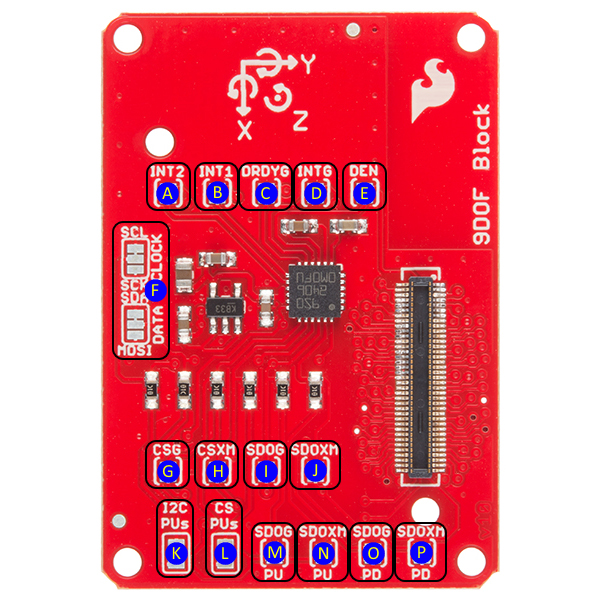
The 9DOF Block has a lot of jumpers on it, but you can use it without understanding or changing any of them. Here's a description of each one:
A (INT2) - Accelerometer/magnetometer interrupt 2. This pin can be configured to change on a number of different conditions. See datasheet pp 58 and 65-67 for more details on configuring the device. Closing this jumper with a solder blob connects the INT2 pin on the LSM9DS0 to GPIO 49 on the Edison.
B (INT1) - Accelerometer/magnetometer interrupt 1. This pin can be configured to change on a number of different conditions. See datasheet pp 58 and 63-65 for more details on configuring the device. Closing this jumper with a solder blob connects the INT2 pin on the LSM9DS0 to GPIO 48 on the Edison.
C (DRDYG) - Data Ready, gyroscope. Closing this jumper connects the pin to GPIO 47. See datasheet page 43 for information on configuring this pin.
D (INTG) - Gyroscope interrupt. This pin can be configured to change on a number of different conditions. Closing this jumper will connect the pin to GPIO 46. See datasheet pages 43 and 47-50 for information on configuring this pin.
E (DEN) - Data enable, gyroscope. Enable or !pause data collection. This pin can safely be ignored. Closing this jumper allows processor control of data collection via GPIO 165.
F (CLOCK/DATA) - I/O interface selection jumpers. Default setting is to I2C1 but cutting the small trace visible between the two upper pads of each jumper and closing the bottom two pads with a solder blob allow the user to route control to SPIDEV2. SPI is currently an unsupported feature and will likely be removed from a future revision.
G (CSG) - SPI chip select, gyroscope. Closing this jumper connects the signal to GPIO 111 on the Edison, which is FS0 on SPIDEV2. The CS pin can be either handled manually or by the driver. SPI is currently an unsupported feature and will likely be removed from a future revision.
H (CSXM) - SPI chip select, accelerometer/magnetometer. Closing this jumper connects the signal to GPIO 110 on the Edison, which is FS1 on SPIDEV2. The CS pin can be either handled manually or by the driver. SPI is currently an unsupported feature and will likely be removed from a future revision.
I (SDOG) - SPI serial data out (MISO), gyroscope. SPI is currently an unsupported feature and will likely be removed from a future revision.
J (SDOXM) - Serial data out (MISO), accelerometer/magnetometer. SPI is currently an unsupported feature and will likely be removed from a future revision.
K (I2C PUs) - Pull-up resistor removal for I2C SDA and SCL lines. Most likely, you won't want to remove these resistors from the system; however, if you have a lot of devices on the I2C bus, you may need to remove some of the pull-ups from the lines to reduce the pull-up strength. (No solder indicates that pull-ups are disabled. Connect all three pads with a solder blob to enable pull-ups.)
L (CS PUs) - Pull-up resistor removal for SPI chip select lines. Normally pull-up resistors should be left in place. SPI is currently an unsupported feature and will likely be removed from a future revision.
M (SDOG PU) - Closed by default, this pin sets the I2C address used by the gyroscope. When closed, the gyroscope's address is 0x6b. When open, jumper SDOG PD (labeled 'O' above) must be closed.
N (SDOXM PU) - Closed by default, this pin sets the I2C address used by the magnetometer/accelerometer. When closed, their collective address is 0x1d. When open, jumper SDOXM PD (labeled 'P' above) must be closed.
O (SDOG PD) - Open by default, this pin sets the I2C address used by the gyroscope. When closed, the gyroscope's address is 0x6a.
P (SDOXM PD) - Open by default, this pin sets the I2C address used by the magnetometer/accelerometer. When closed, their collective address is 0x1e.