SparkFun 5V/1A LiPo Charger/Booster Hookup Guide
Using Multiple Charger Boosters
5V may be fine for microcontrollers, addressable LEDs, and servos, but with motors sometimes some extra kick is required. With electric motors, speed is proportional to voltage, and torque is proportional to current. So if we want robot acceleration we'd want a high torque motor (low resistance), and if we want to go fast we'll need to supply a large voltage. This section shows how to use multiple boosters and what that means for the voltage levels.
The boosters have bypass diodes placed across their outputs. This means that if a negative voltage is presented to the output, it will conduct rather than apply negative voltage to the rails.
This allows the boosters to be placed in series to create voltages larger than 5, with a couple of caveats.
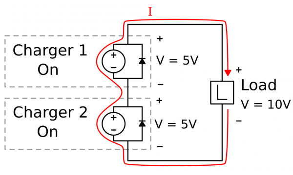
The following two diagrams show how two chargers in series interact. With both chargers on and supplying 5V, the output runs at 10V, and 1 amp is driven through the booster circuit (shown as an ideal supply).
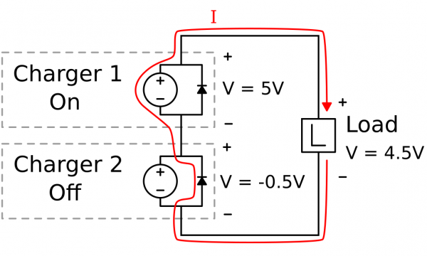
When one booster stops producing voltage, it's still in the current loop and must pass the 1A that the other booster can provide. The protection diodes allow the current to slip by, but at the cost of a diode drop. For these B340A Schottky diodes, that's about 0.5V. The output voltage is now 4.5V.
Increasing Current
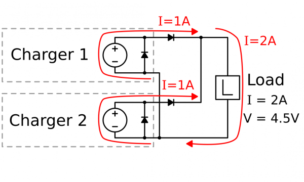
Life gets a little trickier if more current is needed. By supplying your own diodes and "diode OR-ing" the outputs, you can get increased current at the cost of a diode drop, or somewhere around 4.5V. You may get away with just connecting up the outputs but run the risk of back-feeding one output with the other.


