SparkFun 5V/1A LiPo Charger/Booster Hookup Guide
 MTaylor
Hardware Assembly
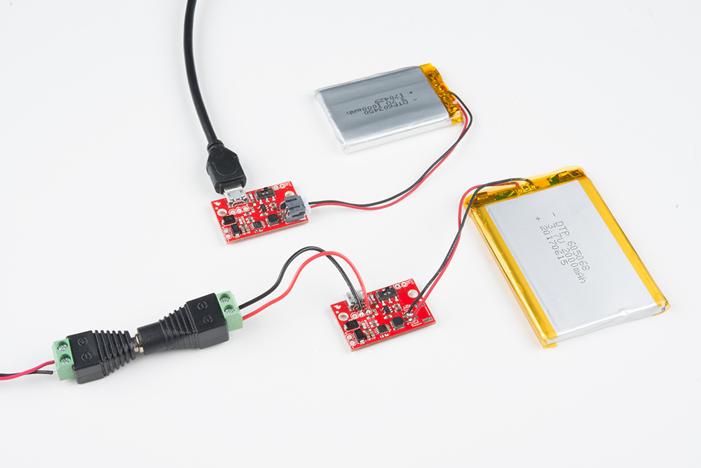
It's easy to get started on your bench. Simply plug the LiPo into the battery JST connector, charge with a micro-B USB supply, and solder your load to the output pins. This section shows some tips and alternate ways to configure the ports.
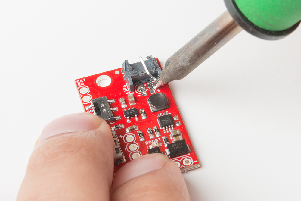
Covered Battery Pins
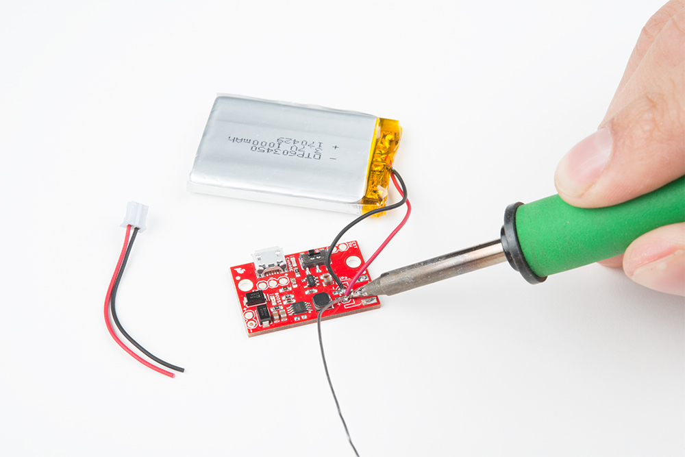
There are a pair of through-holes peeking out from underneath the JST connector. Here's how to safely remove the JST and apply battery leads directly. This also lowers the profile of the circuit board.
Make several small cuts to split the JST housing using a cutter. If you try and take the whole thing off at once, you risk pulling up the pads.
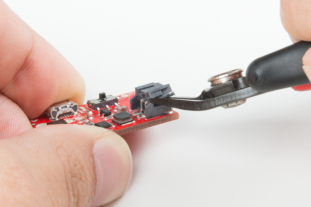
With the top removed, the pins aren't captured in the housing anymore and they can be pulled off with the soldering iron one by one.
Alternatively, you can hot air the JST connector off, but it may melt in the process.
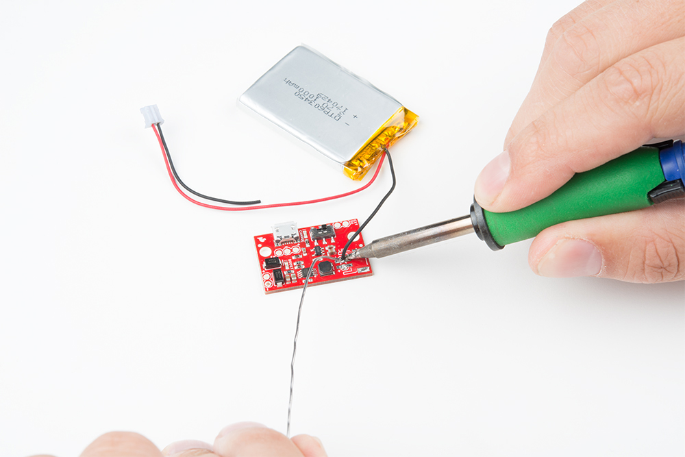
Cut and strip part of the end of the wire. Then solder the end to its respective through hole.
Charge Source Pins
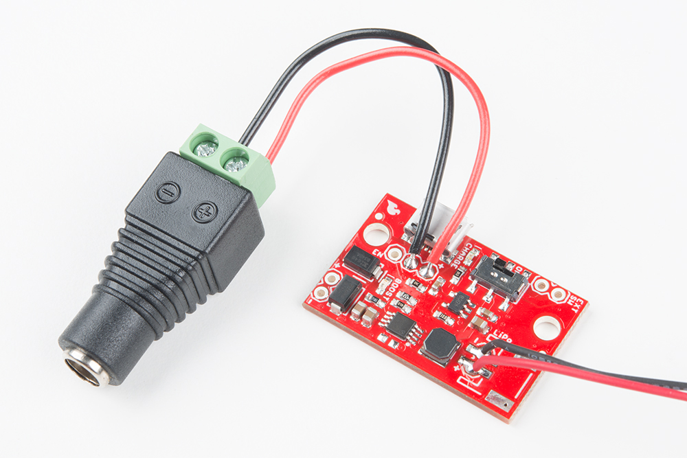
As with the JST port, you may wish to charge your lipos from a source other than a micro-B, such as a 5v barrel or bench supply. The USB port is difficult to remove without damage to the board, so leave it in and just use the '+' and '-' pins provided by soldering some hookup wire to the respective pins. To connect to a barrel jack easily, you could use a female barrel jack adapter.
External Switch Pins
The onboard switch is rated for 600mA. Using the full current output available, this rating will be violated. It won't have any immediate effect and is alright for peaky load with a nominal 500mA draw, but can lead to heat and corrosion depending on your application. If it's found to be a problem, solder a higher current switch (like the SPST rocker switch) into the 'EXT SW' pins.
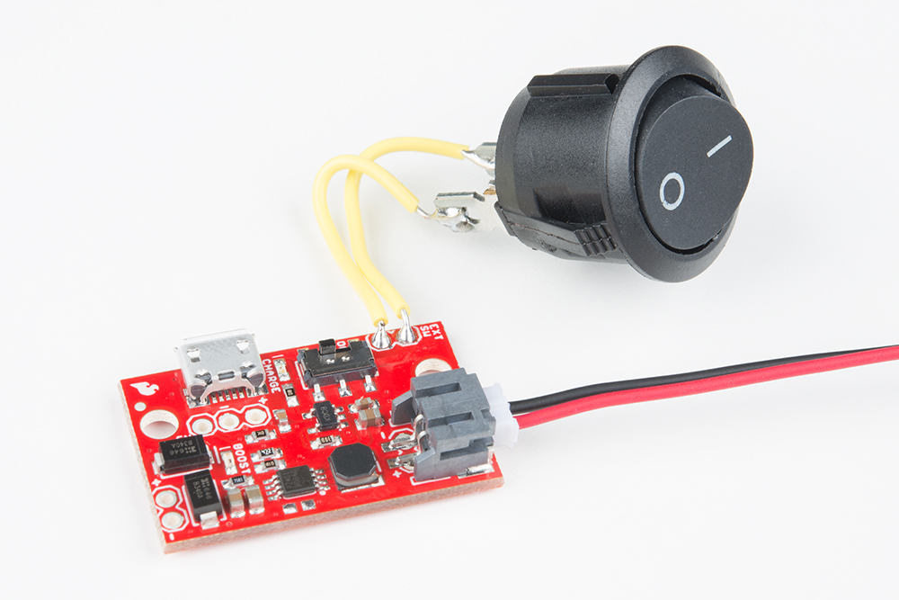
Using a high current switch, the two switches are now in parallel so either one can be used to energize the circuit. If using an external switch, be sure to leave the on-board switch in the OFF position.
Or you can jumper the external switch pins together and use the enable pin to switch power. Further details will be explained in the next section with the enable pin.
Enable Pin
Another method to remove battery load is to use the enable pin on the PAM2401. It's pulled up with a resistor on the board, so leaving it floating will default to an enabled state. To disable, it can be connected to the neighboring ground pin. The pin consumes very little current so a light duty switch (like the mountable slide switch) can be used.
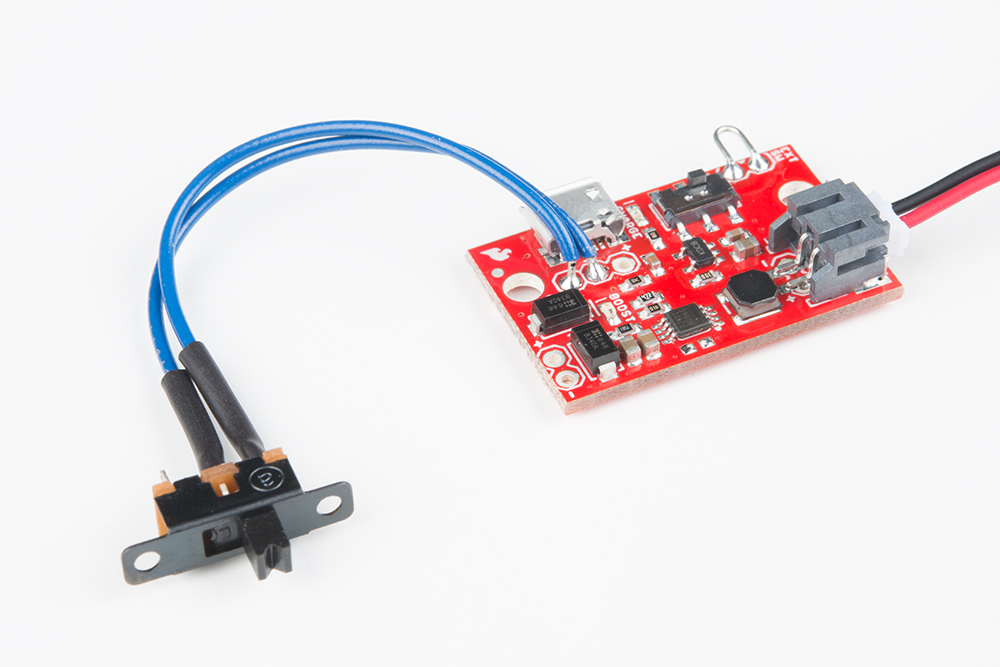
In this configuration, the onboard switch may not be necessary and can be bypassed by putting a jumper in the external switch holes. The battery won't be truly isolated though, and can drain over time. In the disable state, the current draw from the battery is about 6uA so it should take years to discharge.
Alternately, the pin can be driven by a logic source. The pin is 6V tolerant, with a logic-high threshold at 1/2 battery voltage, and a lower threshold of 0.2V.