SparkFun 5V/1A LiPo Charger/Booster Hookup Guide
 MTaylor
Hardware Overview
Parts of the Board
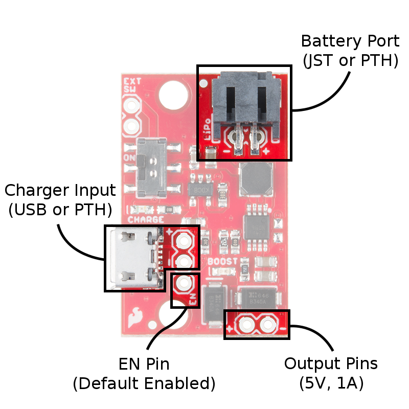
The circuit is constructed by feeding an MCP73831 charge controller IC to the LiPo battery port, and to the input of a PAM2401 boost controller. Power always flows to the boost circuit, so an enable pin is provided to allow the booster to be shut down during charging if desired. Multiple connection types are provided for the battery, charge source, and switch to allow flexibility of application.
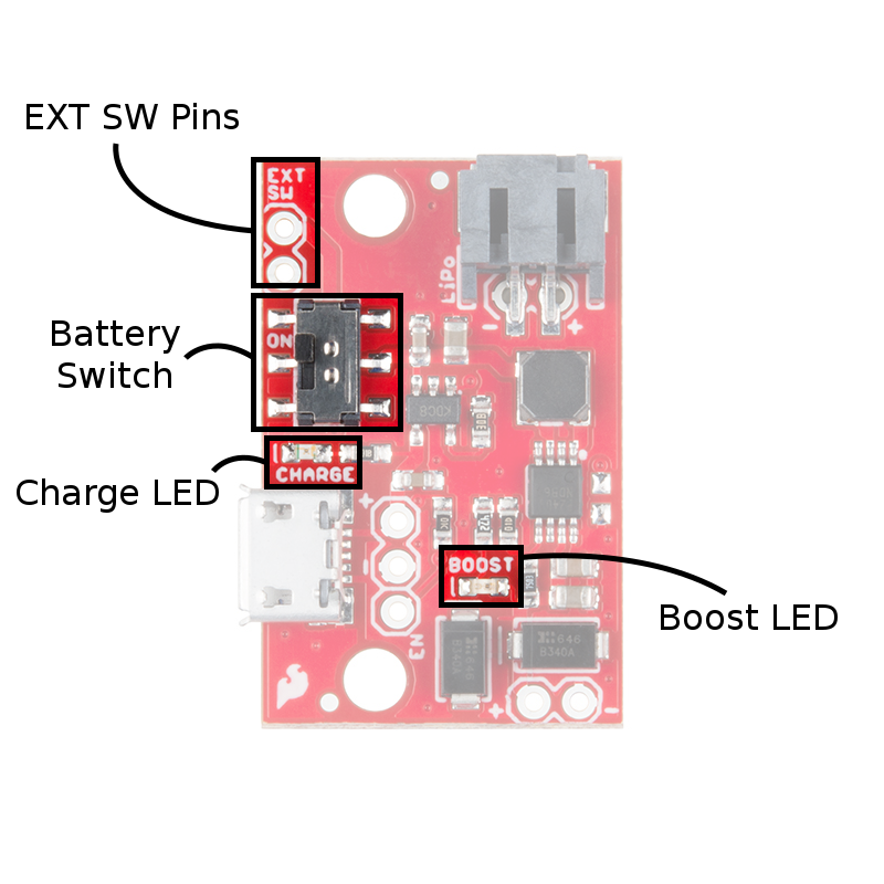
The image below shows the location of the surface mount battery switch and external switch pins which are included to provide an additional option to control the output. Two LEDs are included to provide feedback on system status.
Functions
| Item | Description |
|---|---|
| Output Pins |
Get 5V, 1A out here! The 'OUT' pins are labeled with polarity. |
| Battery Port | Insert a LiPo battery here through the JST connector or solder directly to the PTH pins underneath the connector. These ins are labeled with polarity. |
| Charger Input |
Supply 5V, 500mA here to charge. You can use a micro-B USB cable or solder directly to the PTH pins. These 'IN" pins are labeled with polarity. |
| Battery Switch | The on-board switch is a physical battery disconnect. When in the ON position, the battery is connected to the booster/charger. When flipped to the OFF position, the battery's positive lead is isolated from all electronics, and zero current will be drawn. |
| EXT SW Pins |
These run parallel to on-board battery switch contacts. A higher current switch can be connected through these pins. If you're constantly drawing large currents or want a remote battery disconnect switch, connect it here. |
| EN Pin |
The EN pin is enabled by default. This pin floats high and can be connected to ground to turn the output off. This is useful if your load circuit can't be put into low power mode for charging. |
| Charge LED |
The charge LED indicates blue when the charger IC is attempting to charge the battery. It will turn off when the battery is fully charged. Note: If current is being drawn while the battery is being charged, the charger may think the battery is never quite full and continue sourcing current. |
| Boost LED |
This LED indicates red when voltage is present on the output pins. |
Charge Status LED
The on-board blue CHARGE LED can be used to get an indication of the charge status of your battery. Below is a table of other status indicators depending on the state of the charge IC.
| Charge State | LED status |
| No Battery | Floating (should be OFF, but may flicker) |
| Shutdown | Floating (should be OFF, but may flicker) |
| Charging | ON |
| Charge Complete | OFF |