Sound Reactive EL Wire Costume
 jenfoxbot
Program It!
Connect EL Sequencer to computer via 5V FTDI Breakout Board or cable.
Program the EL Sequencer using the Arduino platform; the EL Sequencer runs an ATmega328p at 8 MHz and 3.3V.
Determine how you want to use the sound detector output(s) to control the EL wire. The sample program below utilizes the gate channel output to turn on the EL wire if there is a sound detected.
For a simple example sketch, you can copy the code below or you can visit the following link.
language:c
// Sound Activated EL Wire Costume
// Blink EL Wire to music and other ambient sound.
//JenFoxBot
void setup() {
  Serial.begin(9600);
  // The EL channels are on pins 2 through 9
  // Initialize the pins as outputs
  pinMode(2, OUTPUT);  // channel A
  pinMode(3, OUTPUT);  // channel B
  pinMode(4, OUTPUT);  // channel C
  pinMode(5, OUTPUT);  // channel D
  pinMode(6, OUTPUT);  // channel E
  pinMode(7, OUTPUT);  // channel F
  pinMode(8, OUTPUT);  // channel G
  pinMode(9, OUTPUT);  // channel H
//Initialize input pins on EL Sequencer
  pinMode(A2, INPUT);
}
void loop()
{
  int amp = digitalRead(A2);

  //If Gate output detects sound, turn EL Wire on
  if(amp == HIGH){

    digitalWrite(2, HIGH); //turn EL channel on
    digitalWrite(3, HIGH);
    digitalWrite(4, HIGH);
    delay(100);
  }

    digitalWrite(2, LOW); //turn EL channel off
    digitalWrite(3, LOW);
    digitalWrite(4, LOW);

}
This program is just one example of what is possible with the SparkFun Sound Detector. Depending on your needs, different responses can be achieved by using the "envelope" and "audio" outputs of the sound detector. The EL Sequencer can individually control up to 8 different EL wire strands using the three sound detector output signals, so there are tons of possibilities to customize your sound-activated outfit!
More information about the sound detector output signals:
The gate channel output is a digital signal that is high when a sound is detected and low when it is quiet. The envelope channel output traces the amplitude of the sound, and the audio output is the voltage directly from the microphone. Check out the plot below for the actual output voltage of the sound detector.
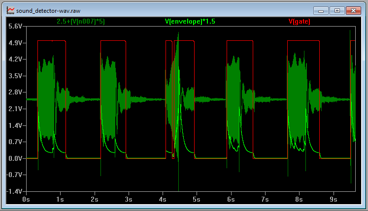
In the photo above, the red trace corresponds to the gate signal output, the light green trace corresponds to the envelope signal output, and the dark green trace corresponds to the audio signal output. More info can be found in the Sound Detector Hookup Guide.