Sound Location with the Qwiic Sound Trigger and the u-blox ZED-F9x
Contributors:
 PaulZC
PaulZC 
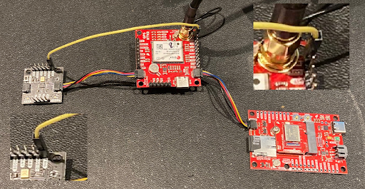
Hardware Connections
- Solder a 6-way row of header pins to the Qwiic Sound Trigger so you can access the TRIG pin.
- Please see the Data Logging Hookup Guide
- Insert the Artemis Processor into the MicroMod Data Logging Carrier Board and secure with the screw.
- Connect your ZED-F9P GNSS breakout to the Carrier Board using a Qwiic cable.
- Connect an antenna to your GNSS board. The antenna must have a clear view of the sky. Extend and feed the cable through a window if you need to.
- Insert a formatted micro-SD card into the socket on the Carrier Board.
- Connect the Qwiic Sound Trigger to the ZED-F9P using a second Qwiic cable.
- Use a jumper cable to connect the TRIG pin on the Qwiic Sound Trigger to the INT pin on the ZED-F9P breakout.
- Connect the Carrier Board to your computer using a USB-C cable.
To minimise I2C bus errors, it is a good idea to open the I2C pull-up split pad links on the MicroMod Data Logging Carrier Board and the u-blox module breakout and the Qwiic Sound Trigger.