smôl Hookup Guide
 PaulZC
GPIO Waterfalling
smôl provides two General Purpose Input / Output signals. These are generally used for power control, allowing individual smôl boards to be completely powered down to minimise the current draw
Just like the SPI Chip Select signals, the two GPIO signals also use waterfalling.
The two GPIO signals are called GPIO0 and GPIO1. On the ESP32 Processor Board, these are connected to GPIO27 and GPIO26 respectively. In Arduino terms, they are D27 and D26, or Digital Pins 27 and 26.
Here are the FPC connections on the smôl ARTIC R2 again:
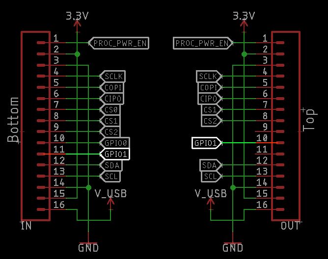
The smôl ARTIC R2 uses GPIO0 for power control and so uses GPIO0 (Pin 10) from the IN connector.
GPIO1 (IN Pin 11) is not used and so is connected directly to the OUT connector but as Pin 10 (not Pin 11).
If the ARTIC R2 is placed immediately above the ESP32 Processor Board in the smôl stack, its Power Enable is connected to ESP32 Digital Pin 27.
If another Peripheral Board were placed above the ARTIC R2 board, it too could use GPIO0 but it would be connected to ESP32 Digital Pin 26 (not 27) thanks to the waterfalling.
The important 'rule' is: Peripheral Boards must be placed above the Processor Board in the smôl stack
If you accidentally place a Peripheral Board below the processor board, no damage will be done. But the Peripheral Board will not function as expected because its GPIO signal will be left floating.
Power Boards are a special case. They only use I2C for communication and so can be placed anywhere in the stack. The natural place for them is below the Processor Board, but you can place them above if you want to.
The smôl Header only has an OUT connector so it needs to go at the very bottom of your stack.