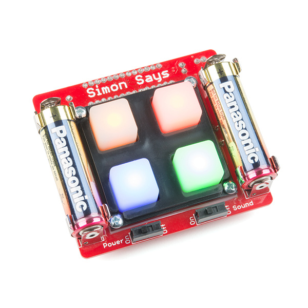
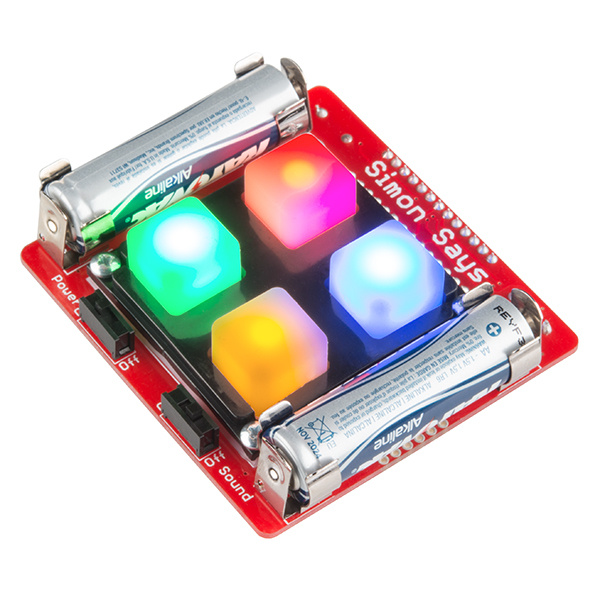
Simon Says Assembly Guide
Introduction
If you've found yourself here, chances are you've purchased one of our many Simon Says Through-Hole soldering kits. This tutorial will help you become familiar with the tools you'll need to build the Simon Says, show you how to build it, and show you how you can take this simple, yet fun, game further with a little bit of programming know-how. The different kits encompassed in this tutorial include:
These kits are all very similar. The only difference is that SparkFun Simon Says - Through-Hole Soldering Kit, you will need to provide your own tools to build it. If you do not have the necessary tools, the Learn to Solder kit comes with everything you need to get started. To make things simple, we'll cover everything from the tools to building the Simon Says all in this tutorial. If you feel comfortable enough with soldering and are just looking for some detailed instructions on how to put your kit together, you may want to skip ahead. However, if you would like to know more about soldering, which tools are best for the job, and how to properly maintain those tools, then read on!
Suggested Reading
If you aren’t familiar with the following concepts, we recommend checking out these tutorials before continuing.
How to Solder: Through-Hole Soldering
Resistors
Polarity
Required Tools
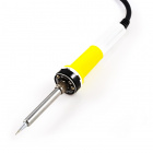
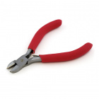
If you've purchased the Simon Says - Through-Hole Kit or Retail Kit, the following is a recommended list of materials you'll need to complete the build. If you have a Learn to Solder: Simon Says, your kit should include all of the following:
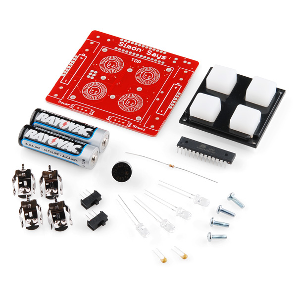
Inside the Simon Says Through-Hole kit, you'll find all the parts for the Simon Says. This includes:
- ATmega328 - pre-programmed with Simon firmware
- Buzzer
- 0.1μF Cap (x2)
- 10K Resistor
- LEDs (x4) (blue, yellow, red, green)
- Slide Switch (x2)
- Battery Clips (x4)
- AA Batteries (x2)
- Button pad
- Bezel
- Standoffs and screws (x4)
- Simon Says - Through-Hole PCB
Missing any parts? Sometimes one of those tiny little components can get misplaced. If you're missing any parts contact our customer service team, and we'll get you the missing parts in a jiffy.
Quickstart - Soldering Basics and Advice
There are some basic tips that will help you achieve the best solder connection possible, help keep your soldering iron in good condition and also keep you safe. For starters, it is best to keep your iron unplugged when not using it. Leaving soldering irons on for long periods of time will wear out the tip much quicker. They are also very easy to forget about when left plugged in and can be a potential fire hazard.
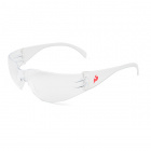
With that said, put on your safety glasses and plug your iron in to let it warm up before using it. Allow it to warm up for about 30 seconds - 1 minute. The tip of the iron is normally 700°F, hot enough to melt metal solder. It is normal for the handle of the soldering iron to heat up a bit. Hold it like a pencil and move your hand further away from the tip if the heat is uncomfortable.
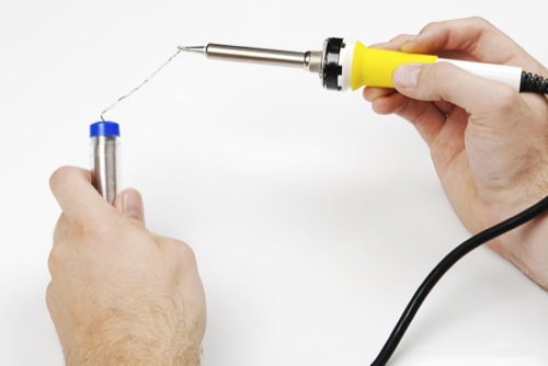
There isn't any indicator to let you know when the iron is ready. NEVER TOUCH THE TIP OF THE IRON TO SEE IF IT'S ON. The best way to test if your iron is warmed up and ready is to melt a little solder on the end. If it melts easily, you're good to go. The solder smokes because the rosin inside the solder is burning off - it's not harmful. If you have trouble getting the solder to melt on the tip, let it warm up a little bit longer.
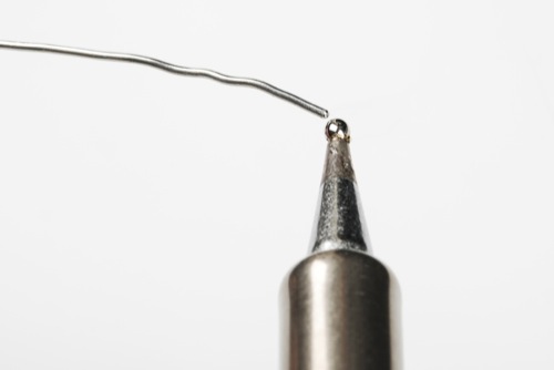
Here's a close up of the solder once the solder is able to melt on the soldering iron tip.
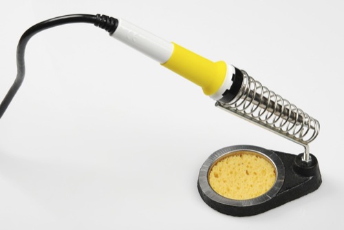
The next bit of advice is always keep your iron in its stand while you're not using it. Setting down your iron on your workspace can be a major hazard. Not only can you burn the other items on your workbench, but you can also set your arm down on it and get a gnarly burn (I speak from experience). Your iron has a home, and we're all better off when you keep it there.
Maintaining Your Soldering Iron
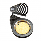
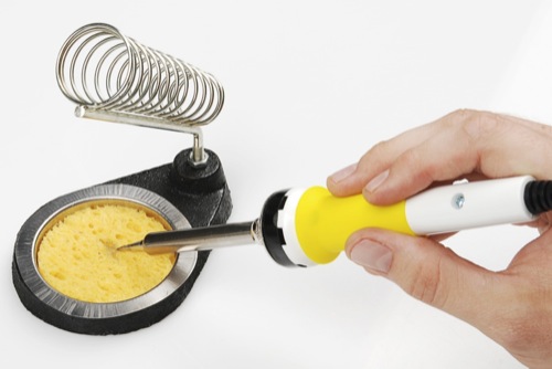
You'll notice that on your stand there is a little pool with a sponge in it. This sponge plays a very important role in soldering. As you solder, old solder tends to clump up and lose its ability to melt and flow properly. It can also build up a nasty residue on your iron tip and corrode it to the point where it won't accept solder any more. That's where the sponge comes in handy.
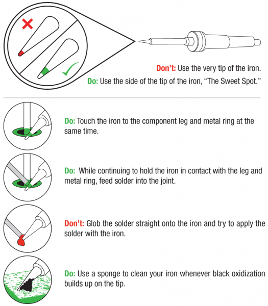
Dampen it in a sink or using a water bottle. It doesn't need to be soaked, just wet enough to pull solder off your iron. Now, very gently, wipe the excess solder off onto the sponge. Avoid jamming the tip into the sponge or leaving the tip on the sponge for more than a few seconds. Doing so could result in holes in your tip, which ultimately ruins your iron. You should periodically clean your tip as you're soldering. This will make your solder connections look nicer and will increase the life of your iron. To increase the life of your iron even more, we recommend using a brass sponge instead of a regular one. Expansion and contraction of the tip, from the cool water, tends to wear it out over time.
Now that we've covered proper soldering iron handling and care, let's go over how to properly use it. There is a correct way to solder, and it takes lots of practice to master. Getting it right early on will make your soldering experience a lot more fun. Be sure to follow these bits of advice while your putting your kit together.
Soldering Advice: How to Properly Use a Soldering Iron
Below are some tips that show how to properly use the iron.
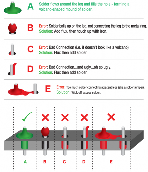
Soldering Advice: How to Create an Ideal Solder Joint
Below are some tips on creating the best solder connection possible.
If you still have some uncertainties about soldering, check out the tutorial below. There is a video for those of you who are of the visual learning variety.
How to Solder: Through-Hole Soldering
Quickstart - Your First Component
We'll go over over in detail how to solder on the first part. Then we'll show you which parts go where and let you have at it. The booklet that comes with the Simon Says has been carefully crafted and goes over the assembly in lots of detail. We'll follow along here. Click on the image for a larger view, or you can download the entire guide here.
10kΩ Resistor
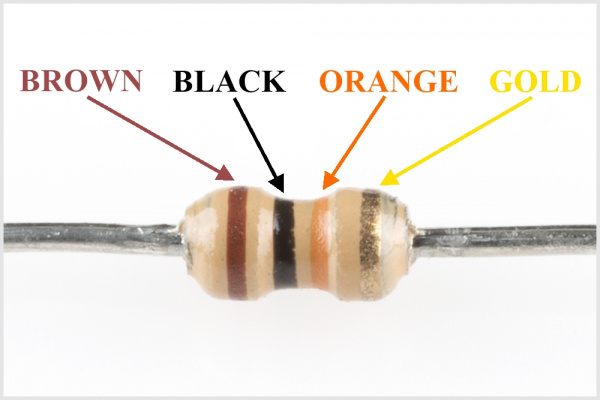
Locate the 10kΩ resistor.
If you look closely, it has a specific pattern of stripes on it: BROWN, BLACK, ORANGE, GOLD.
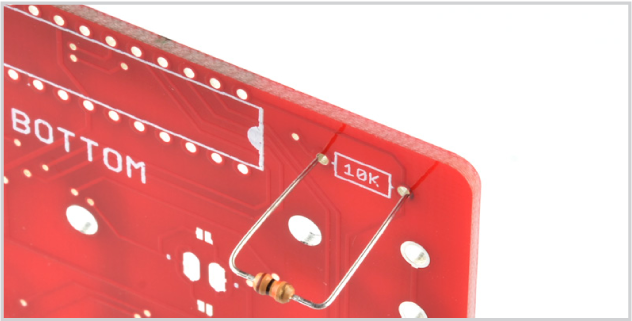
Bend the legs downward.
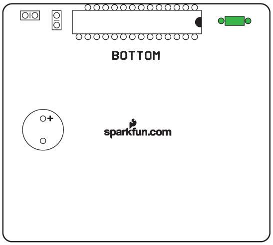
Locate the 10kΩ resistor position on the board
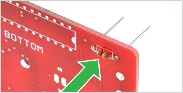
Insert the resistor into the PCB.
Push the resistor in so it is nearly flush with the board.
| Polarized Component | Pay special attention to the component’s markings indicating how to place it on the PCB. Polarized components can only be connected to a circuit in one direction. |
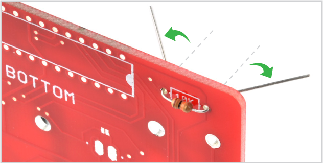
Slightly bend the legs outward to hold it in place.
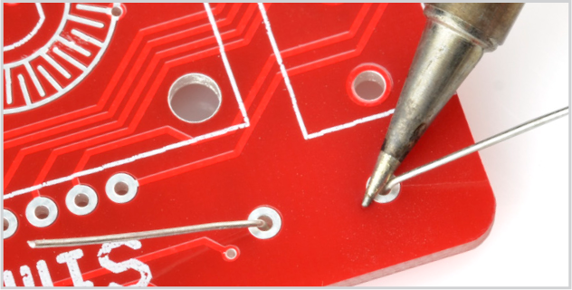
Flip the board over. Hold the soldering iron's "Sweet Spot" so it touches both the leg and the metal ring. Hold for 2 seconds.
Feed solder into the joint.
First, pull away the solder. Second, pull away the iron.
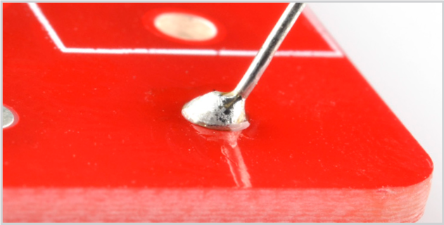
Your solder joints should look like this - a tiny volcano.
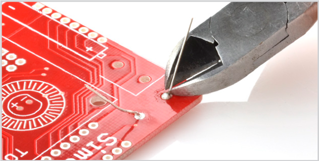
Clip off any excess legs.
Capacitors
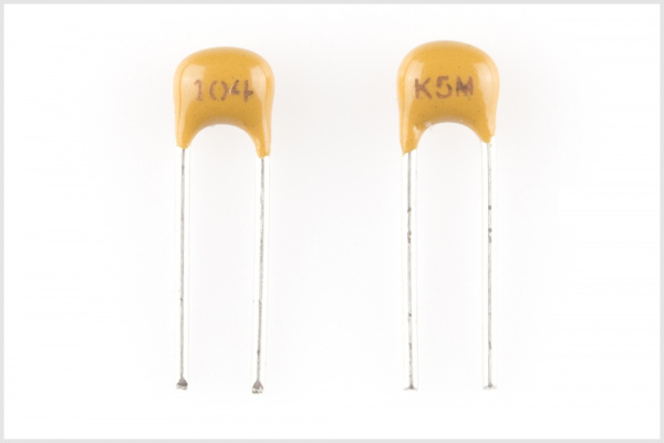
Locate the two 0.1uF decoupling capacitors. These look a little different than resistors. They have two leads than come down off the bottom of the component, and they have the markings “104” on them. (also note, the bottom side may have some other letters, like “K5M”). They look like this:
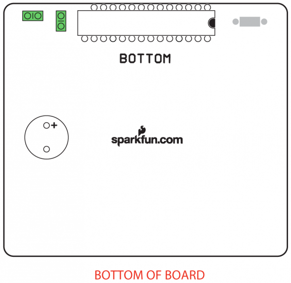
Locate their positions on the PCB:
Insert the capacitors, flip the board over to the bottom side, and solder the pins just like the resistor.
Microcontroller
| Polarized Component | Pay special attention to the component’s markings indicating how to place it on the PCB. Polarized components can only be connected to a circuit in one direction. |
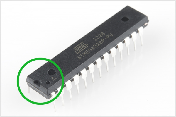
Locate the microcontroller. This component is polarized, which means we need to take extra care to place it in the board properly. Notice the notch on the image below.
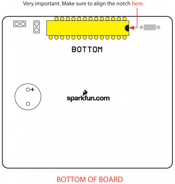
Looking at the bottom of the board, insert the microcontroller . Make sure that the notch on the chip aligns with the white silkscreen on the board. To avoid having it inserted backwards, we cut off a pin.
Flip the board over and solder all of the microcontroller's pins to the board.
Buzzer
| Polarized Component | Pay special attention to the component’s markings indicating how to place it on the PCB. Polarized components can only be connected to a circuit in one direction. |
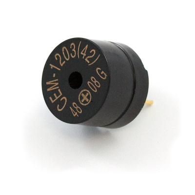
Locate the piezo buzzer.
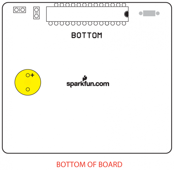
Locate the position on the PCB. Note the "+" on the buzzer . The "+" on the buzzer should align with the white "+" on the board.
Flip the board over and solder the buzzer's pins.
LEDs
| Polarized Component | Pay special attention to the component’s markings indicating how to place it on the PCB. Polarized components can only be connected to a circuit in one direction. |
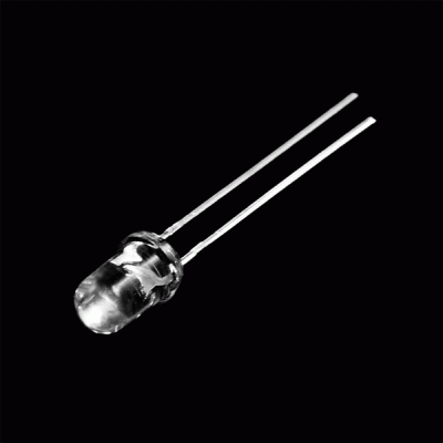
Locate the four LEDs.
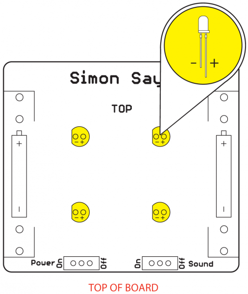
The LEDs are polarized. This means there are “-” and “+” legs. Each LED has a short leg and a long leg. The short leg goes into the hole labeled "-". Locate their positions on the PCB.
Insert the four LEDs into the top of the board. Also, make sure each of them sits flush with the PCB. Then solder them into place.
For more information about polarization with LEDs, please check out this tutorial on Diode and LED Polarity.
Battery Clips
| Polarized Component | Pay special attention to the component’s markings indicating how to place it on the PCB. Polarized components can only be connected to a circuit in one direction. |
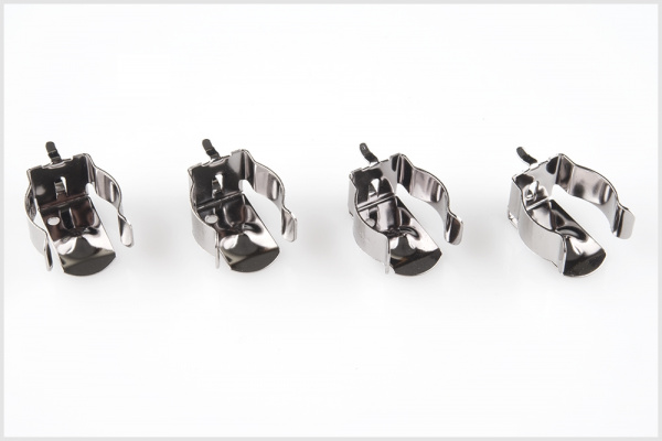
Locate the four battery clips.
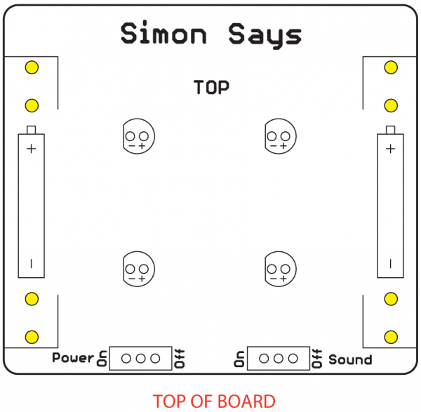
Locate their positions on the PCB. Insert the battery clips . Make sure clips point toward each other so the battery fits.
Ensure clips are flat against the board. Then solder from the bottom of the board.
Switches
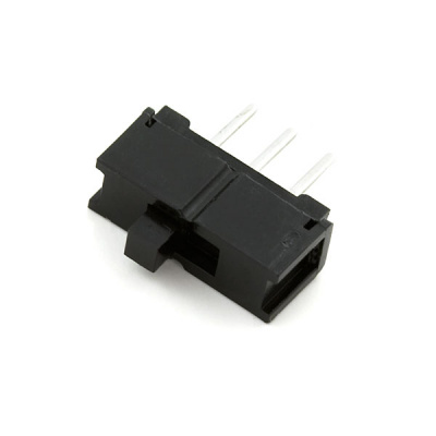
Locate the two slide switches.
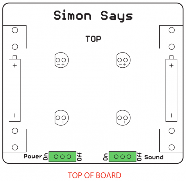
Locate their positions on the PCB. Looking at the top of the board, insert the switches. Keep the iron tip away from the black plastic! Plastic melts easily.
Flip the board over. Then begin to solder.
Final Assembly
| Polarized Component | Pay special attention to the component’s markings indicating how to place it on the PCB. Polarized components can only be connected to a circuit in one direction. |
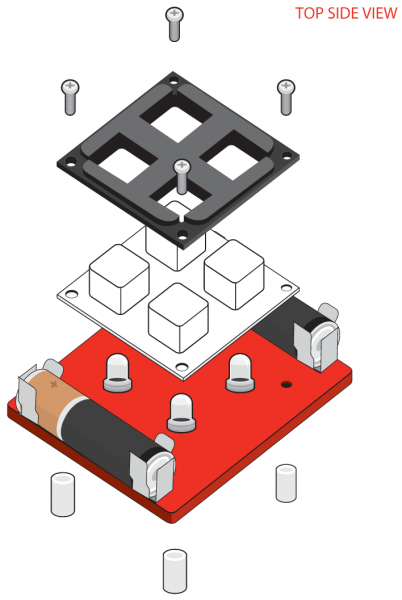
Locate the button pad, bezel, screws, standoffs, and AA batteries. You will need to:
- Attach the button pad to the top of the board. Make sure to lay the rubber button over the LEDs.
- Attach the bezel over the button pad with notches for the screws pointing up.
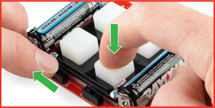
- Insert the screws through the bezel and button pad. Then twist standoffs onto the protruding screw. No screwdriver is necessary. Hand tighten.
- Insert the batteries , following "+" and "-" indicators on the board.
Insert the components as shown in the image below.
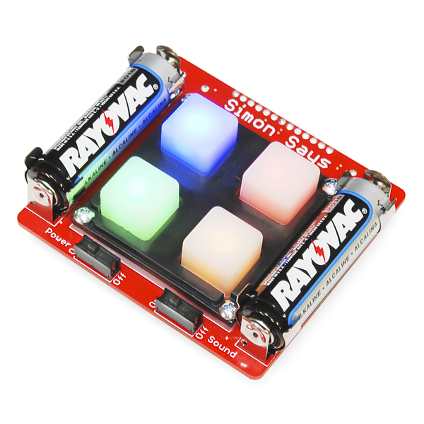
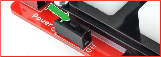
With that, you should have a fully functional Simon Says that you built yourself! Turn it on by flipping the "Power" and "Sound" switch to the "On" position to see if it works.
If something is not working (i.e. an LED won't light up), please check out our troubleshooting section.
BONUS: Extra Fun!
Did you know that your Simon is much more than it seems? As an example of how the Simon is more than just a game, we have included special features in the code. Just for fun, try this out. Don't worry, it won't change your Simon permanently.
Turn the power switch to the "Off" position.
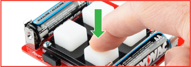
Press any one button.
While holding the button down, turn the Simon Says back on to test out one of the special modes that we have included!
Troubleshooting
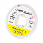
If your Simon doesn't work right off the bat, don't fret. There are many ways that your board could have an error on it. Look over these troubleshooting tips to help diagnose the problem. This section also goes over how to use the solder wick that came with your kit. This is like an eraser for soldering mistakes, and it can come in very handy if a mistake is made.
LEDs
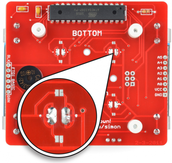
LED(s) not lighting up even though you have a sufficient solder joint? Don't fret, there is an easy way to fix it! The most common cause of a failed LED is incorrect polarity. We have designed a special trick into the Simon PCB's design. You can simply cut the two traces and close two jumpers. This will swap the polarity without having to remove the LED.
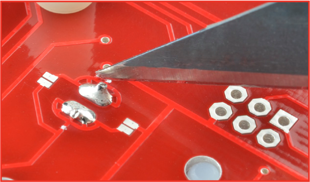
Using a hobby knife, cut both exposed traces directly over the white dots. To test, try using a multimeter set to measure continuity to probe the trace between the pads and LED pins. This can help determine if the traces have been fully cut.
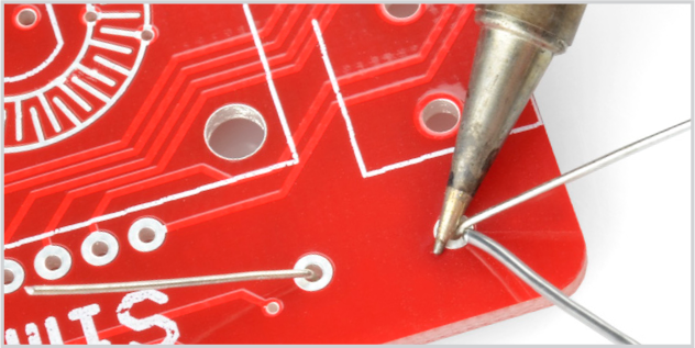
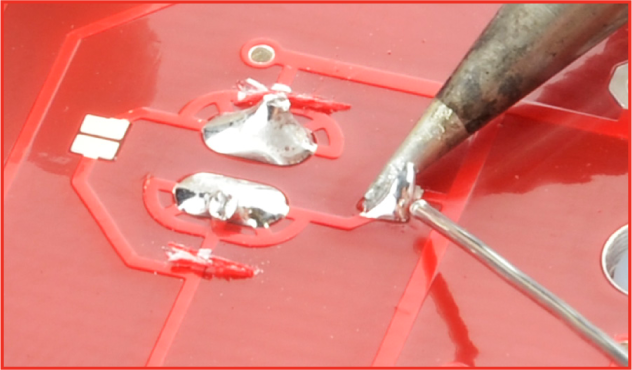
Using a soldering iron, close both jumper pads with some solder. The image below shows an example of one of the pads being closed.
Solder Jumpers
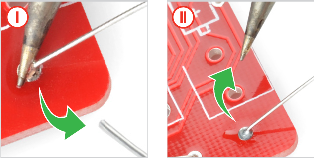
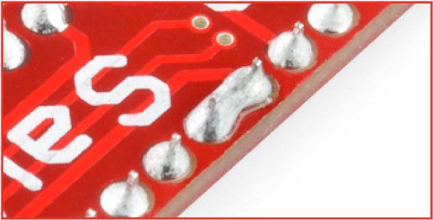
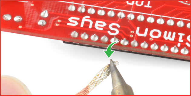
Did you accidentally solder a jumper between two legs where it should not be included? Don't fret. Here is a simple process using solder wick to remove the excess solder.
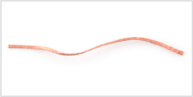
Locate a solder wick.
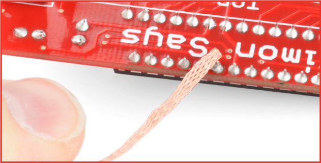
Place solder wick on top of solder.
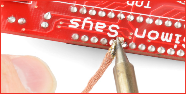
Place iron on top of solder wick. Hold for 3-4 seconds.
Once the solder begins to flow into the wick, pull the wick and iron away at the same time.
Resources and Going Further
Wrapping It All Up
I hope this has been a fun learning adventure. Soldering is a much easier than it may seem, and can be a useful tool for many trades and hobbies. If you still feel like you need some more help you can check out the video below. It goes over the same steps as are mentioned here, however, sometimes seeing someone else do it is easier than trying to explain it.
Bootloader Note: Reprogramming the ATmega328P Microcontroller w/ Arduino!
Now that you've successfully got your Simon Says up and running, it's time to incorporate it into your own project!
Arduino IDE
This ATmega328P comes pre-programmed with the Simon code as well as the STK500 serial bootloader. This serial bootloader will allow you to re-program the Simon game using the Arduino IDE. Selecting the "LilyPad Arduino w/ ATMega328" bootloader that was burned to the Atmega328P chip allows the Simon to be re-programmed to do many different things! You can write code to change your Simon into a new unique project. Try browsing our GitHub repository containing the default example code and additional examples:
Parts to Upload Code
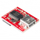
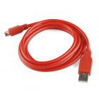
To upload new code to the board, we require additional components that are not included in the kit.
To learn how to use the Simon Says with the Arduino IDE, we have a few tutorials. To get started, it is recommended to start with this tutorial:
Simon Says Experiments
For more information, check out the resources below:
- Schematic (PDF)
- Eagle Files (ZIP)
- Soldering Tutorial
- Simon Says Assembly Instructions (PDF)
- Building the Simon PTH Kit Demo Video
- Bootloader Note (PDF)
- Prototyping Simon Says on a BreadBoard w/ the Sparkfun SIK V3.3 for Arduino
- Simon Says Default Code (ZIP)
- Simon Says GitHub Repository - (Design Files & Example Code)
Need some inspiration for your next project? Check out some of these related tutorials:
Simon Splosion Wireless
Simon Tilts Assembly Guide
Simon Says Experiments
Or check out these blog posts for ideas
If you still have any questions or comments, please leave them below in the comments section. Happy soldering!
