Rotary Switch Potentiometer Hookup Guide
Introduction
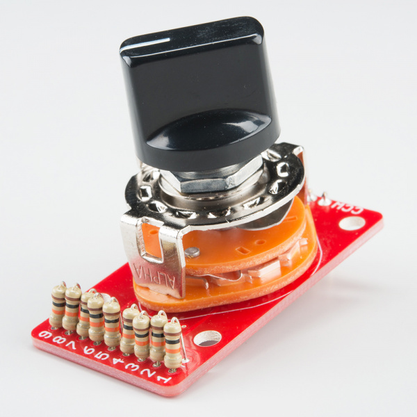
The Rotary Switch Potentiometer is a board that allows you to add some resistors to our one of our 10-position rotary switches, turning it into a potentiometer with ten discrete steps.
If you're wondering why a potentiometer with ten steps would be useful, keep reading! We've got a couple of examples that illustrate applications where this board is more useful than a regular, continuous potentiometer.
In This Tutorial
We'll start by examining what a potentiometer is, and a couple of common circuits built from them. We'll then proceed to build a couple of example projects: one using a microcontroller, and another using the board in an analog demonstration.
Materials
We'll cover several different examples in this hookup guide, all built from the same basic parts. If you want to follow along, you'll need these components:
- The Rotary Switch Potentiometer breakout board.
- A 1x10 position rotary switch.
- An Assortment of resistors.
- Straight or right-angle snappable headers.
- A control knob or chickenhead knob.
- The digital project uses a RedBoard and a 7-segment LED display.
- One of the analog projects uses a SparkFun Sound Detector.
Suggested Reading
- Our Voltage Dividers tutorial introduces one of the circuits commonly built using potentiometers.
- The Sound Detector Hookup Guide explains how to use and configure the Sound Detector.
- Potentiometers are a type of Resistor.
- The Geofex.com article The Secret Life of Pots describes the internal mechanisms of a potentiometer, and explores some of the more esoteric varieties.
- The Wikipedia article about decibels contains some relevant background information.
