Rotary Switch Potentiometer Hookup Guide
 Byron J.
Background and Theory
A potentiometer (or pot for short) is an electronic component that functions as a variable resistor. They are usually drawn in schematics with the following symbol.
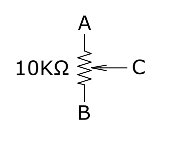
The main component within the pot is a resistor, illustrated between terminals A and B, above. There is a third terminal, C, that can travel along the resistance. As it moves, the resistance between it and the ends of the resistance change. Conectptually, you can think of it like this:
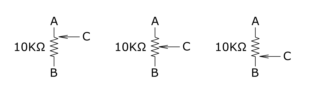
In the first illustration, the moving element is at one end of the resistor, and there will be very little resistance between terminals A and C, with 10KΩ between B and C. In the middle illustration, the moving terminal is at the center of the resistor, so we'll have 5KΩ from terminal C to both A and B. Finally, the moving terminal is at the far end of the resistor, with 10KΩ from A to C, and 0Ω from B to C.
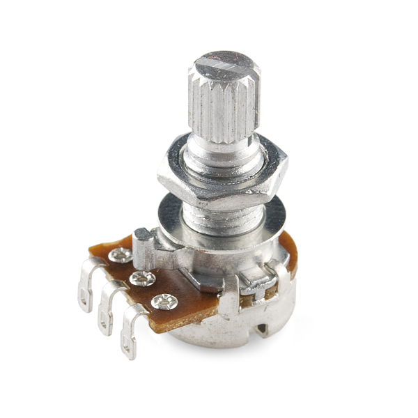
Pots come in a wide variety of shapes and sizes. The most common is probably the rotary potentiometer.
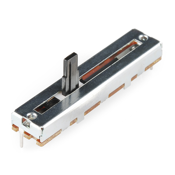
Another common type of potentiometer is the linear, or slide pot.
Regardless of the physical configuration, the moving terminal is called the wiper, while the other terminals are known as the ends, or described in terms of the physical orientation of the pot, such as clockwise and counterclockwise for a rotary pot, or top and bottom on a slider.
Pots come in a wide variety of shapes, sizes, resistance values, and electronic configurations.
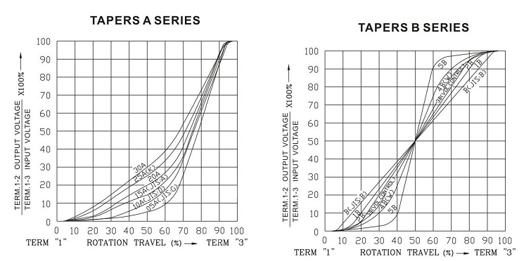
The way the resistance changes relative to the position of the wiper is known as the taper of the pot. A garden variety pot usually has a linear taper, where the change of resistance corresponds to the wiper position. Another commonly found taper is the logarithmic or audio taper, where the change in resistance moves more quickly at one end than the other -- they are commonly found as volume controls, where the logarithmic taper corresponds to the acuity of our hearing.
The following graph shows audio tapers on the left, and linear (curve "B(JIS:B)") on the right, among several other tapers.
Potentiometer Applications
There are two principal circuits built using pots.
Variable Resistor
If we put the pot in our circuit with only the wiper and one end connected, it functions as a variable resistor. The overall resistance is directly related to the position of the wiper. There are a couple of different schematic symbols used to represent variable resistors, shown below.
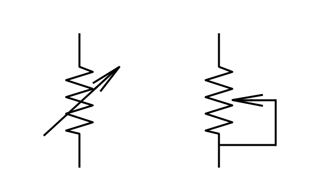
If you're building a circuit that uses a variable resistor, consider what might happen in the circuit if the wiper loses contact with the resistor element, for instance, if a speck of dirt falls into the pot. Some circuits will misbehave if the resistor suddenly disappears like that. You'll notice that the second symbol above ties the wiper to one terminal -- should the wiper lose contact, the circuit jumps to the overall value of the pot, rather than an open circuit.
Voltage Divider
Another common circuit built with potentiometers is the voltage divider.
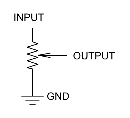
Voltage dividers are useful for reducing the voltage of a signal -- as the name implies, they divide the input by a constant value. If you use a divider in the feedback loop of an opamp, you can turn the division into multiplication, building a variable gain amplifier.
We have a lot more information about divider circuits in our voltage divider tutorial.
The Rotary Potentiometer Breakout
Some applications require pots that are hard to find, calling for specific resistance values, or custom tapers. The Rotary Switch Potentiometer board allows you to populate your own resistors, to help match situations where ordinary parts aren't available or suitable. They can also be used in situations where you want distinct steps or selections, such as being able to consistently select to a value.
An assembled rotary switch potentiometer can be used as either a variable resistance or a voltage divider. We'll explore both types of circuit in the following sections.