Rotary Switch Potentiometer Hookup Guide
 Byron J.
Introduction
The Rotary Switch Potentiometer is a board that allows you to add some resistors to our one of our 10-position rotary switches, turning it into a potentiometer with ten discrete steps.
If you're wondering why a potentiometer with ten steps would be useful, keep reading! We've got a couple of examples that illustrate applications where this board is more useful than a regular, continuous potentiometer.
In This Tutorial
We'll start by examining what a potentiometer is, and a couple of common circuits built from them. We'll then proceed to build a couple of example projects: one using a microcontroller, and another using the board in an analog demonstration.
Materials
We'll cover several different examples in this hookup guide, all built from the same basic parts. If you want to follow along, you'll need these components:
- The Rotary Switch Potentiometer breakout board.
- A 1x10 position rotary switch.
- An Assortment of resistors.
- Straight or right-angle snappable headers.
- A control knob or chickenhead knob.
- The digital project uses a RedBoard and a 7-segment LED display.
- One of the analog projects uses a SparkFun Sound Detector.
Suggested Reading
- Our Voltage Dividers tutorial introduces one of the circuits commonly built using potentiometers.
- The Sound Detector Hookup Guide explains how to use and configure the Sound Detector.
- Potentiometers are a type of Resistor.
- The Geofex.com article The Secret Life of Pots describes the internal mechanisms of a potentiometer, and explores some of the more esoteric varieties.
- The Wikipedia article about decibels contains some relevant background information.
Background and Theory
A potentiometer (or pot for short) is an electronic component that functions as a variable resistor. They are usually drawn in schematics with the following symbol.
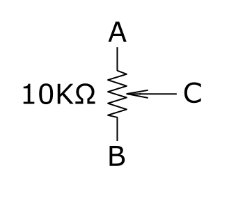
The main component within the pot is a resistor, illustrated between terminals A and B, above. There is a third terminal, C, that can travel along the resistance. As it moves, the resistance between it and the ends of the resistance change. Conectptually, you can think of it like this:
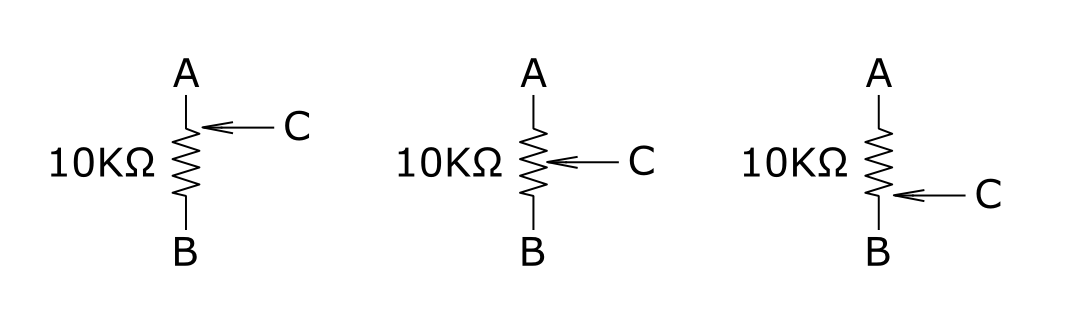
In the first illustration, the moving element is at one end of the resistor, and there will be very little resistance between terminals A and C, with 10KΩ between B and C. In the middle illustration, the moving terminal is at the center of the resistor, so we'll have 5KΩ from terminal C to both A and B. Finally, the moving terminal is at the far end of the resistor, with 10KΩ from A to C, and 0Ω from B to C.
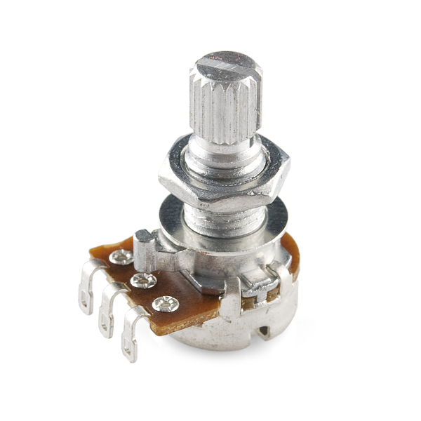
Pots come in a wide variety of shapes and sizes. The most common is probably the rotary potentiometer.
Another common type of potentiometer is the linear, or slide pot.
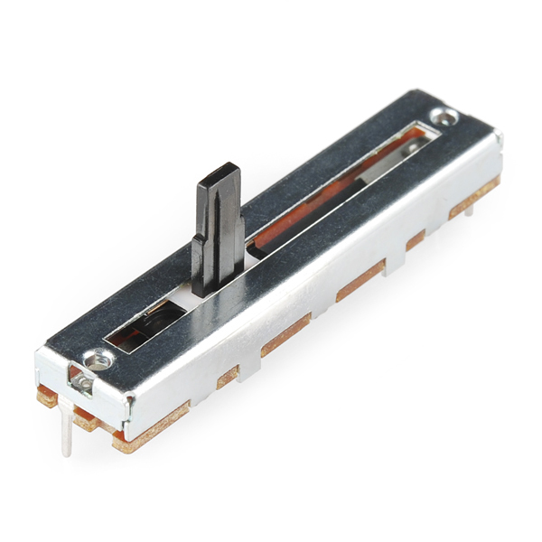
Regardless of the physical configuration, the moving terminal is called the wiper, while the other terminals are known as the ends, or described in terms of the physical orientation of the pot, such as clockwise and counterclockwise for a rotary pot, or top and bottom on a slider.
Pots come in a wide variety of shapes, sizes, resistance values, and electronic configurations.
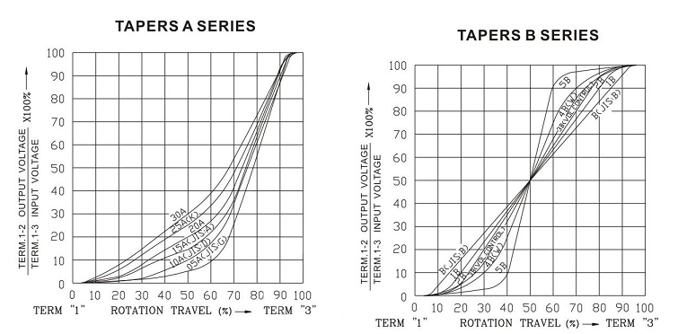
The way the resistance changes relative to the position of the wiper is known as the taper of the pot. A garden variety pot usually has a linear taper, where the change of resistance corresponds to the wiper position. Another commonly found taper is the logarithmic or audio taper, where the change in resistance moves more quickly at one end than the other -- they are commonly found as volume controls, where the logarithmic taper corresponds to the acuity of our hearing.
The following graph shows audio tapers on the left, and linear (curve "B(JIS:B)") on the right, among several other tapers.
Potentiometer Applications
There are two principal circuits built using pots.
Variable Resistor
If we put the pot in our circuit with only the wiper and one end connected, it functions as a variable resistor. The overall resistance is directly related to the position of the wiper. There are a couple of different schematic symbols used to represent variable resistors, shown below.
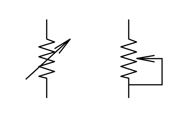
If you're building a circuit that uses a variable resistor, consider what might happen in the circuit if the wiper loses contact with the resistor element, for instance, if a speck of dirt falls into the pot. Some circuits will misbehave if the resistor suddenly disappears like that. You'll notice that the second symbol above ties the wiper to one terminal -- should the wiper lose contact, the circuit jumps to the overall value of the pot, rather than an open circuit.
Voltage Divider
Another common circuit built with potentiometers is the voltage divider.
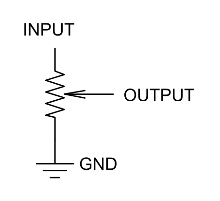
Voltage dividers are useful for reducing the voltage of a signal -- as the name implies, they divide the input by a constant value. If you use a divider in the feedback loop of an opamp, you can turn the division into multiplication, building a variable gain amplifier.
We have a lot more information about divider circuits in our voltage divider tutorial.
The Rotary Potentiometer Breakout
Some applications require pots that are hard to find, calling for specific resistance values, or custom tapers. The Rotary Switch Potentiometer board allows you to populate your own resistors, to help match situations where ordinary parts aren't available or suitable. They can also be used in situations where you want distinct steps or selections, such as being able to consistently select to a value.
An assembled rotary switch potentiometer can be used as either a variable resistance or a voltage divider. We'll explore both types of circuit in the following sections.
Assembly
Assembly of the Rotary Switch Potentiometer board is fairly straightforward.
First, solder the rotary switch inside the outline on the top of the board.
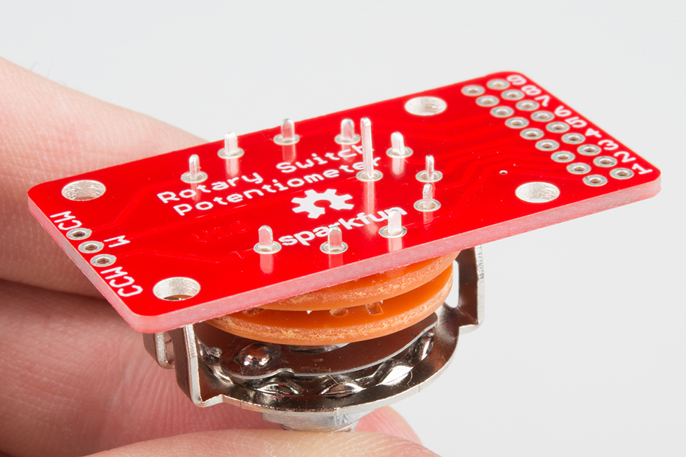
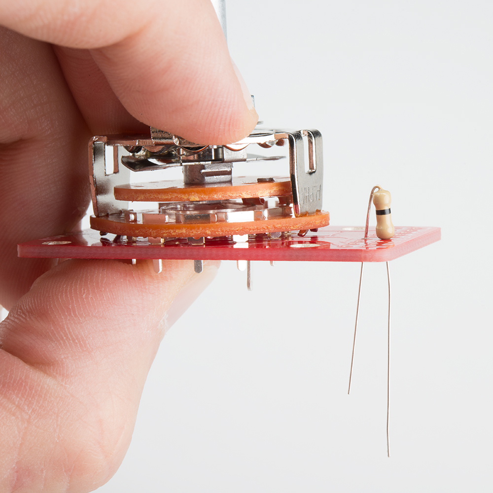
Next, solder your resistors in the positions marked 1 through 9. These resistors are bent like a hair pin, and soldered in place "standing up."
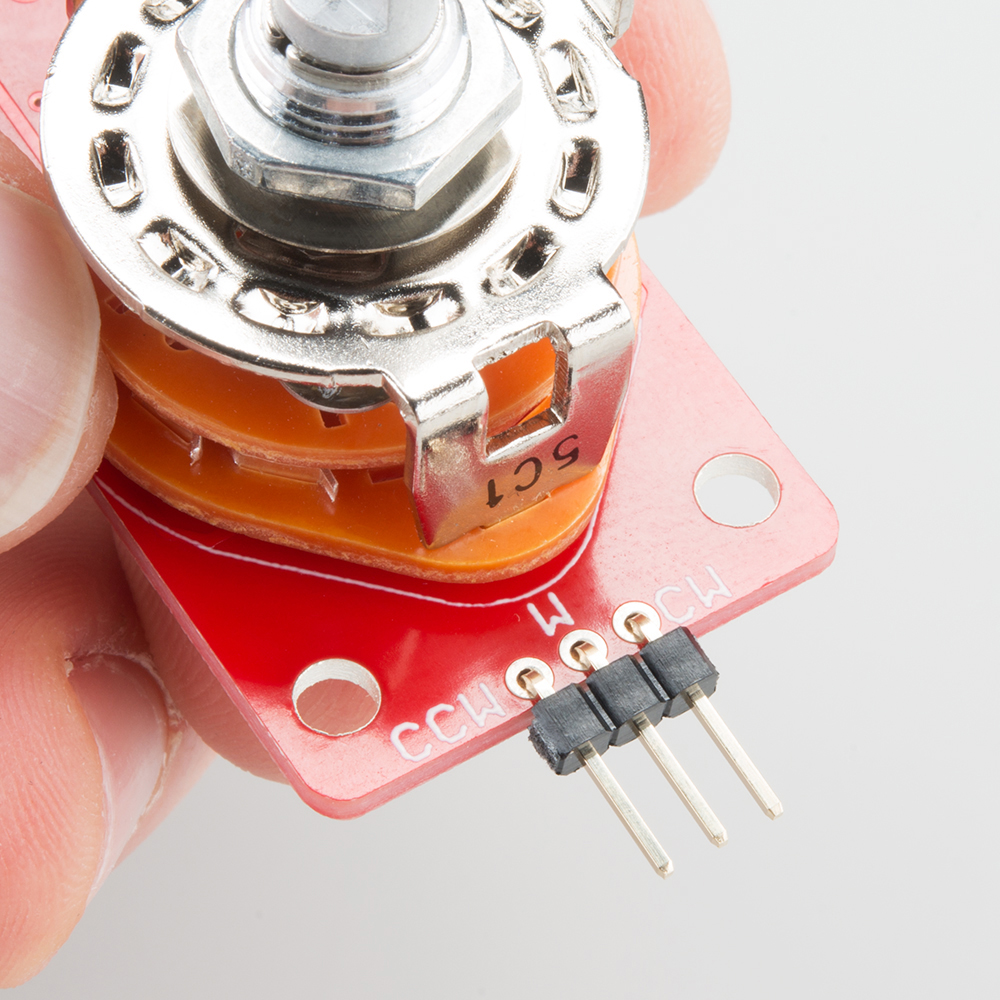
Next, attach leads or a connector to the three pins on the other end of the board. For this hookup guide, we'll be using three pins from snappable headers. These solder pads are labeled with their function:
CCWCounterclockwise end of resistor string.WWiper.CWClockwise end of resistor string.
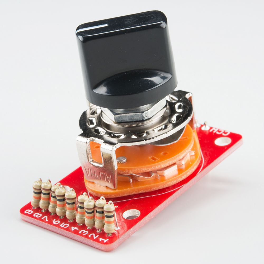
Finally, top it off with a knob of your choice.
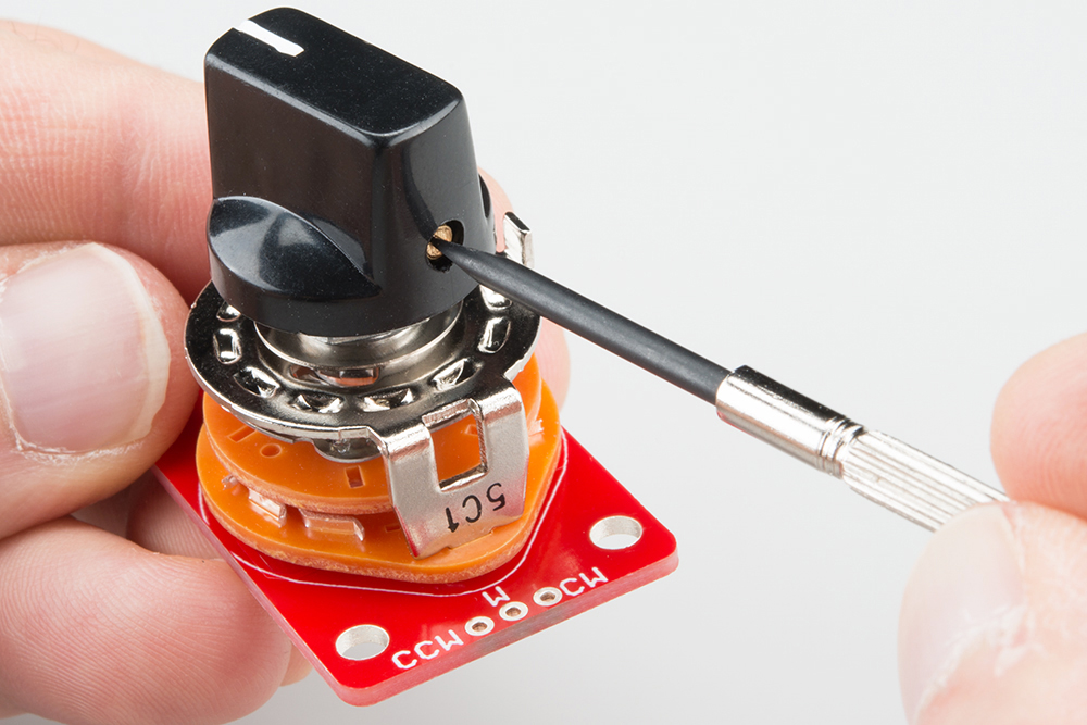
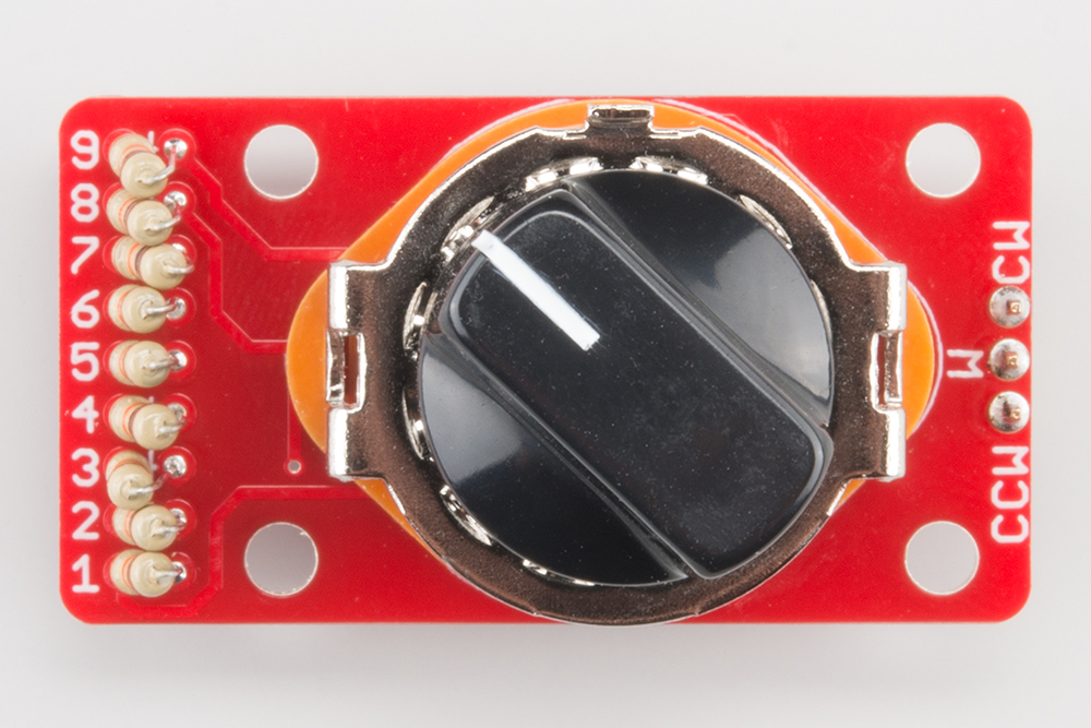
When it's complete, it will look something like this
You'll notice that we haven't explained exactly which resistors you'll want to use. That's really the purpose of this board! You can select resistors that fit your needs, and you'll select different resistors depending on what you're trying to do.
The "Cheat Sheet"
To help with the math involved in deploying the Rotary Switch Potentiometer, we have developed a spreadsheet that helps calculate resistor values. It's in the "theory" subdirectory on the GitHub Repo.
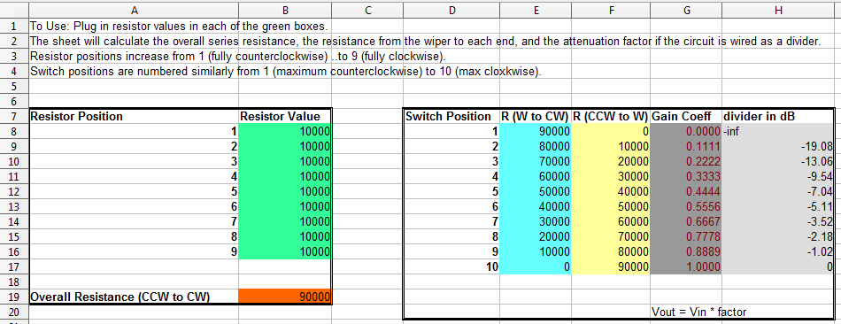
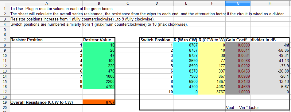
You enter the resistor values in the green cells, and the sheet calculates the resulting circuits. For purposes of discussion, we've simply plugged in 10KΩ for each resistor, above.
- The orange cell contains the total series resistance -- this is the value of an equivalent regular potentiometer. The nine 10K resistors add up to 90K total.
- The blue and yellow cells calculate the resistance from the wiper (
wterminal) to each end contact (ccwis counterclockwise end,cwis clockwise). These are the values the describe the circuit if you're using it as a variable resistance. - The dark grey cells show the arithmetic gain coefficient if the circuit is wired as a voltage divider. For instance, if the switch it at the 4th position, the output voltage will be the input voltage multiplied by 0.333.
- The light grey cells express the gain coefficient in decibels. For the moment, just notice that it changes very quickly between positions 1 to 4, then more slowly from 4 to 10. We'll explore the reasons why, and present a solution in a later section.
Spreadsheet Numbering
The board uses a ten position switch, which has nine locations in between the stops where resistors are installed. The resistor positions are all aligned on the edge of the board, and labeled 1 through 9. When you're working with the spreadsheet, notice that the box on the left side denotes the nine resistor locations, while the box on the right side corresponds to the ten switch positions. Both sets of numbers increase with the clockwise rotation of the switch. One is the furthest counterclockwise, ten is the furthest clockwise, an depicted below.

Some Notes About Installation
If you're building the Rotary Switch Potentiometer into some device, you'll want to consider how you mount it.
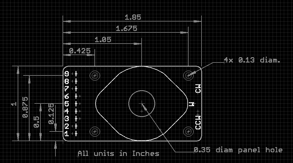
To put the switch in a control panel, you can drill a 3/8" (9.5mm) diameter hole, and use the hex nut to secure the switch to the panel. The PCB is 1 inch wide, the same width as the body of the switch itself. This allows it to fit behind control panels, such as the 1.75" vertical unit used by 19" telecom racks, or the 1.5" width of an API 200 or 500 series module.
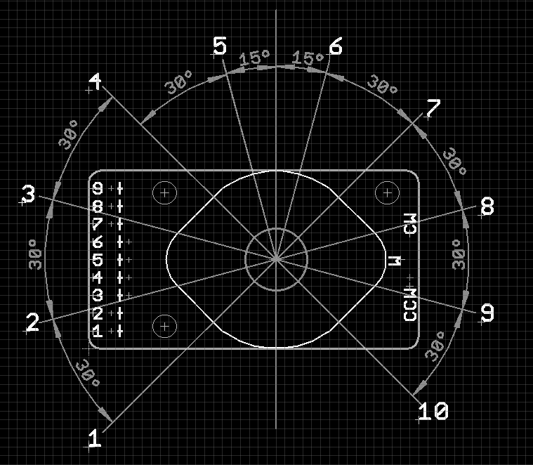
If you're designing a front panel, you might want to put numbers or tick marks around the switch. In order to get those marks in the right place, it's important to know the angles of the switch positions. On a regular control knob, the indicator line is opposite the setscrew, and the knob is usually installed with the setscrew on the flat side of the switch shaft. With the knob installed this way, and viewing the board with the resistors on the left edge, the pointer on the knob will point to the "half-hour" spaces on the clock face, from 7:30, around to 4:30 (or, said differently, in 30° increments, starting + and - 15° away from vertical).
If you don't have a panel, but want secure the board, it also has four mounting holes that accept 4-40 machine screws. And, of course, there are always the old standby solutions of two-sided foam tape, or hot-melt glue!
Understanding how to mount the board, and with the spreadsheet in hand, let's examine some applications that use the Rotary Switch Potentiometer.
Project I: 10 Item Selector
The first project we'll build is based off a comment we received on the Decade Resistance Kit. The idea was posed to build a selector that allows for the selection of ten distinct steps. It's probably not the best application for the decade box, but a great example for the Rotary Switch Potentiometer board.
We'll connect the board as a voltage divider between Vcc and ground, and add resistors to produce ten even steps. Ten even steps means nine of the same value resistor.
We don't want the divider to consume too much current, so we want the overall series resistance to be reasonably high. Using 10KΩ resistors gives us 90KΩ total. It will draw a modest 55 µA from 5V.
At 5V, this results in 0.555V per click of the switch, or about 113 ADC counts.
The switch was then wired as a voltage divider, and connected to ADC 0 on a RedBoard. We added a red 7-segment display on some unused port pins to show the switch setting. A description of the connections is in the sample sketch, below.
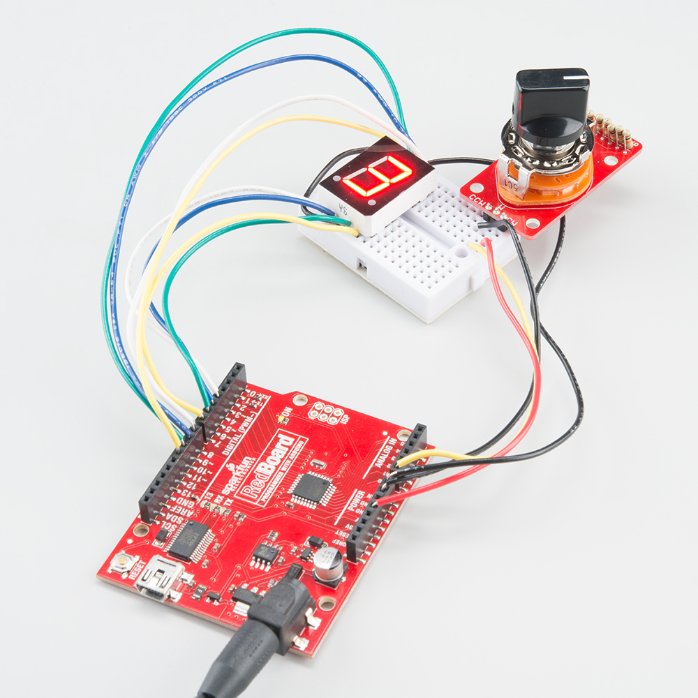
The code is fairly simple.
- It reads the ADC input.
- It does some math to translate the ADC value into the 0 to 9 range.
- It draws the step number by turning on the proper LEDs in the 7-segment display.
Here is the sample sketch.
language:c
/******************************************************************************
one_of_ten.ino
Rotary Switch Potentiometer Example
By Byron Jacquot @ SparkFun Electronics
April 21, 2015
https://github.com/sparkfun/Rotary_Switch_Potentiometer

Demonstrates using the Rotary Switch Potentiometer breakout board
with a microcontroller, to build a 10 position selector switch.

The Rotary Switch Potentiometer is a breakout board that adds 9 resistors to a
10 position rotary switch, to make a custom-taper, stepped potentiometer.  This
example uses 9 10KOhm resistors, and connects the rotary switch potentiometer
to an analog input.  The input is periodically scanned, and the current step
number is displayed on a 7-segment LED.

Development environment specifics:
This was developed using Arduino IDE 1.6.1
Using an Uno-compatible SparkFun RedBoard with a rotary switch potentiometer and
a 7-segment LED.

This code is beerware; if you see me (or any other SparkFun employee) at the
local, and you've found our code helpful, please buy us a round!

Distributed as-is; no warranty is given.
******************************************************************************/

/******************************************************************************
 Hardware connections
 --------------------

The test configuration was wired as follows:

The Rotary Switch Potentiometer board was populated with 10K resistors in
every position.  It was connected to the RedBoard as follows:

RedBoard pin : Rotary Switch Potentiometer Pin
----------------------------------------------
GND          : CCW
A0           : W
5V           : CW

GPIO pins on the RedBoard drove the 7-segment display.  See the 7-segment
display datasheet for the pin number assignment
(https://cdn.sparkfun.com/datasheets/Components/LED/YSD-160AR4B-8.pdf)

RedBoard pin : Rotary Switch Potentiometer Pin
----------------------------------------------
GND          : 3, 8 LED Anodes
4            : 1, segment E
5            : 2, segment D
6            : 4, segment C
7            : 5, decimal point
8            : 6, segment B
9            : 7, segment A
10           : 9, segment F
11           : 10, segment G

******************************************************************************/

// Bitmaps for display digits 0 through 9.
// Pin ordering corresponds to the connections described in the table above.
// This data is treated as active high - we'll invert it
// when it's applied to the GPIO pins for the common-anode display
static const uint8_t font[10] = {0x77, 0x14, 0xb3, 0xb6, 0xd4, 0xe6, 0xe7, 0x34, 0xf7, 0xf4 };

// void drawLED(uint8_t val)
// Takes an input value and renders it on the 7-segment diaplay
// by driving each pin to the appropriate logic level for the character,
// as stored in the table above.
//
// It accepts a uint8_t as input, and truncates it to the 0-9 range.
void drawLED(uint8_t val)
{
  uint8_t idx = val % 10; // truncate input to 0 to 9 range.

  uint8_t mask = 0x01;
  for(uint8_t pin = 4; pin <= 11; pin++)
  {
    // Starting at output pin 4, step through to pin 11.
    // For each pin, check whether the corresponding bit in the font array
    // is set, and if so, illuminate that LED.
    //
    // LED has inverse response - logic low turns it ON.
    // So if a bit in the font is high, set that pin low
    if(font[idx] & mask)
    {
      digitalWrite(pin, LOW);
    }
    else
    {
      digitalWrite(pin, HIGH);
    }

    mask <<= 1;
  }
}

void setup() {
// put your setup code here, to run once:

  Serial.begin(9600);

  // initialize pins 4 through 11 as outputs.
  pinMode(4, OUTPUT);
  pinMode(5, OUTPUT);
  pinMode(6, OUTPUT);
  pinMode(7, OUTPUT);

  pinMode(8, OUTPUT);
  pinMode(9, OUTPUT);
  pinMode(10, OUTPUT);
  pinMode(11, OUTPUT);
}

void loop()
{
  // put your main code here, to run repeatedly:
  uint16_t input;
  uint16_t val;

  // read the ADC
  input = analogRead(0);

  // Translate ADC value from 0-1023 to 0-9.
  // This implements the proportion
  // input/1023 = val/9.
  // One "step" of the pot is about 113 ADC counts.
  // We're adding 65 (1/2 of 113) to the input value, so that the
  // input is in the middle of the window, rather than right at the edge, so values
  // are stable and solid.
  val = (input+56)*9/1023;

  // Take the calculated value and display it.
  drawLED(val);
}
To expand on this example, we could add several more switches and displays, to build a sort of digital decade box -- a switch for the ones digit, a switch for the tens digit, and so on.
Project II: Analog Amplitude Control
The Rotary Switch Potentiometer is also useful in a variety of amplitude control situations.
In many disciplines where amplitude is important, it is often expressed in decibels (known as dB for short). We're not going to get too deep into the particulars here - the Wikipedia Article is much more detailed and complete.
There are a couple of things to keep in mind when describing things in terms of decibels.
The first thing is that decibels behave logarithmically, reducing large changes to regular changes in the decibel scale. In acoustics, if a sound doubles in pressure, it increases by 6 dB SPL. Each time it doubles, that's 6 additional dB. Because our auditory systems have extremely wide dynamic range, we can perceive sounds over a pressure range of greater than 1,000,000:1, or 100 dB SPL.
Also, the term "decibel" by itself simply describes the relative amplitude of two signals -- decibels are used in many different disciplines, such as acoustics, optics, and radio transmission. To recognize these differences, different suffixes are added. dB-SPL describes the amplitude of sound, while dBZ is used to describe the reflected signal in weather radar. A more complete list of different dB measurements can be found at Wikipedia. In order to communicate accurately, be sure to use the appropriate suffix.
If you don't firmly grasp decibels right here, keep reading, as they'll become more obvious as we explore the following examples.
Decibel Attenuation
The first amplitude control circuit that we'll build with the Rotary Switch Potentiometer is a resistor divider, with steps that are graduated to about 6 dB per click of the switch. A voltage divider that is configured to reduce signal amplitude by a particular amount is also known as an attenuator.
Playing with the values from the Resistor Pack, we find that we get roughly 6 dB attenuation per step if each resistor is about double the value of it's predecessor. Picking only values in the kit, we find a reasonable fit in a series of resistors of 10, 22 and 47 Ohms, then 100, 220, and 470, and so on.
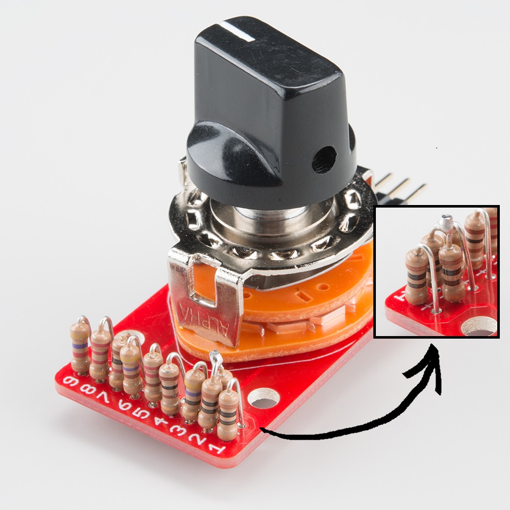
You'll notice that the attenuation per step (the light gray column) isn't exactly 6 dB, but it is pretty close. By limiting ourselves to the resistors in the kit, we only have a few values to pick from. You may have also noticed that the kit is lacking a 22Ω resistor -- as a substitute, we've installed two 10Ω resistors in series (shown in the photo inset). If you want to make a more precise attenuator, you can switch to 1% (or even 0.1%) tolerance resistors, which come in many more values.
Decibel Gain
The reverse of an attenuator is a variable gain amplifier. Where dividers and attenuators can only reduce the voltage, by adding an amplifier, we can also increase the voltage.
The SparkFun Sound Detector is a small board with a microphone, an amplifier stage, and some signal conditioning to indicate the presence of sound. The board can be made more or less sensitive by installing a resistor to change the gain of the amplifier stage. There are tables of suggested fixed resistor values illustrated in the Sound Detector Hookup guide.
While we could install a regular linear-taper pot for the calibration resistor, we'd find that most of the change was bunched up at one end of the rotation. The rest of the travel would have only a tiny effect. Alternately, we could install an audio-taper pot in reverse. The change would be more obvious, but turning the pot up (clockwise) would make the circuit less sensitive -- somewhat counterintuitive. There are "reverse audio" taper pots, but they can be hard to find. Instead, we'll use the Rotary Switch Potentiometer board to build a gain control.
If you take a close look at the tables in the sound detector hookup guide, you'll notice that with R3 installed we can only reduce the gain. For gain that can go both up and down, we'll remove R3. From there, let's look at resistor values that make the sound detector configurable over a significant range. As with the attenuator described above, let's shoot for about 6 dB per step.
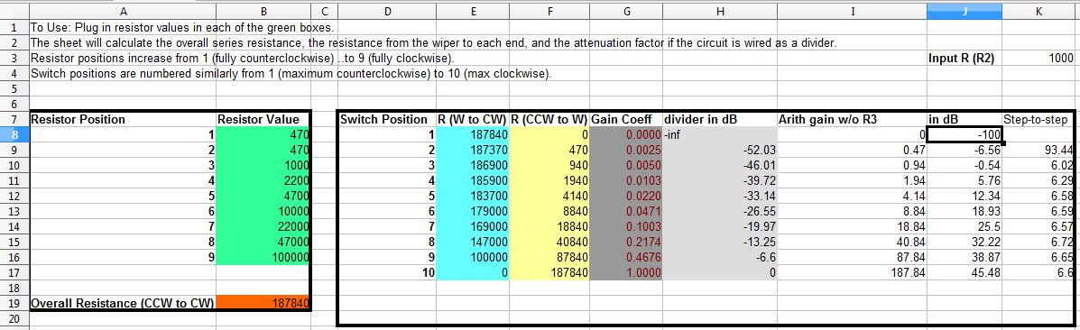
This sheet adds some new columns that calculate the behavior of the sound detector, including the arithmetic gain, gain in dB, and the relative change from step-to-step. Looking at that step-to-step gain column, you'll notice that the first step is very large, because the furthest counterclockwise setting has a gain of zero, effectively turning the amplifier off.
At the 9th position, the gain is 38.87 dB, very close to the 40 dB of the plain Sound Detector - we have added one step above, and eight below.
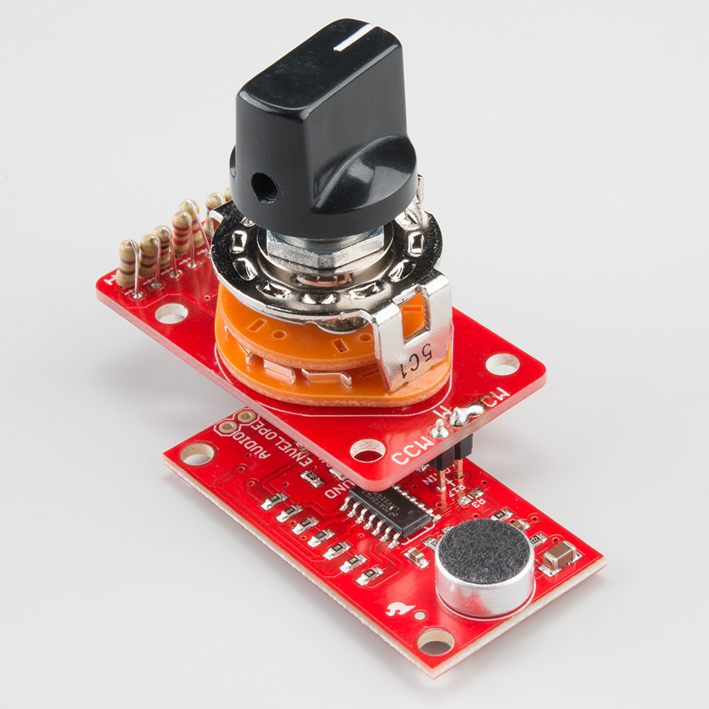
As mentioned in our description of variable resistors, you'll notice that the wiper (W) and clockwise (CW) pins have been joined with a solder blob. The CCW and W pins are installed in the R17 space via a 2-pin header, and R3 was removed entirely.
The combination behaves as we would expect - turning down the knob reduces the sensitivity, so that the detector doesn't trigger on quieter sounds. Turning the knob all the way up makes the detector so sensitive that the air conditioning background noise at the author's workbench triggers the detector intermittently.
Resources and Going Further
From here, it's up to you to dream up uses for the Rotary Switch Potentiometer. It's a handy board when you need ten easily repeatable settings, nonstandard resistance values, or want to craft custom response tapers.
Resources
- If you're still not convinced that the Rotary Switch Potentiometer is right for your application, we also have regular rotary and slide pots.
- If you want to use the rotary switch without the resistors, we have a simple breakout PCB for that, too.
- The Rotary Switch Potentiometer GitHub Repository contains the PCB design files, the sample sketch, and the spreadsheet for calculating resistor values.
Going Further
- Elliott Sound Products have a very detailed article about potentiometer types and applications.