RGB Panel Hookup Guide
 jimblom
Hardware Hookup
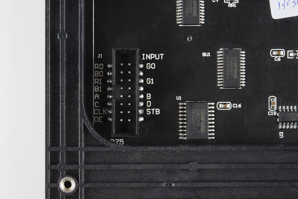
Before we can get into the code portion, there's quite a bit of wiring to do. The RGB panels have a pair of 16-pin (2x8) IDC connectors, and we need to wire up to most of those pins. Conveniently, both panels have the connector pins labeled (the unlabeled pins are ground). As we're hooking up to the panel, make sure you use the connector labeled Input. The labeling may be slightly different depending on the manufacturer.

Hookup Table
Here are the pin connections between LED panel connector and Arduino:
| Panel Pin Label | Cable Connector Pin # | Arduino Uno (Atmega328P) Pin |
Arduino Mega 2560 Pin |
Notes |
|---|---|---|---|---|
| R0 | 1 | 2 | 24 | Red Data (columns 1-16) |
| G0 | 2 | 3 | 25 | Green Data (columns 1-16) |
| B0 | 3 | 4 | 26 | Blue Data (columns 1-16) |
| GND | 4 | GND | Ground | |
| R1 | 5 | 5 | 27 | Red Data (columns 17-32) |
| G1 | 6 | 6 | 28 | Green Data (columns 17-32) |
| B1 | 7 | 7 | 29 | Blue Data (columns 17-32) |
| GND | 8 | GND | Ground | |
| A | 9 | A0 | Demux Input A0 | |
| B | 10 | A1 | Demux Input A1 | |
| C | 11 | A2 | Demux Input A2 | |
| D | 12 | A3 | Demux Input E1, E3 (32x32 panels only) | |
| CLK | 13 | 11 | LED Drivers' Clock | |
| STB | 14 | 10 | LED Drivers' Latch | |
| OE | 15 | 9 | LED Drivers' Output Enable | |
| GND | 16 | GND | Ground | |
For a more step-by-step approach, follow along below. We use male-to-male premium jumper wires to wire between the included ribbon cable and our Arduino.
Connect Data Pins: R0, B0, G0, R1, G1, and B1
These LED driver (shift register) data pins are hard-coded in the Arduino library and can't be moved. As listed in the table above, R0, G0, B0, R1, G1, and B1 go to the Arduino Uno's pins 2 through 7 respectively. If you're wiring the panel up to an Arduino Mega, these pins should be connected to pins 24-29 respectively.
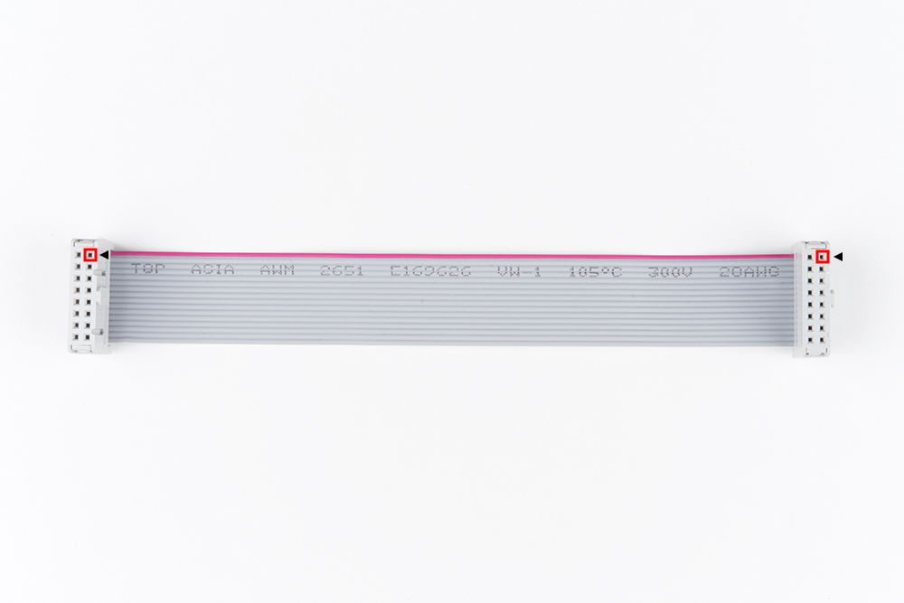
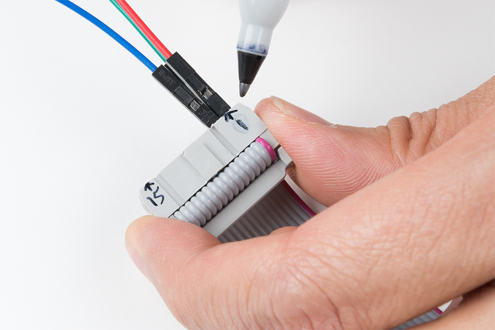
For reference when wiring the pins, try looking down at the IDC connector with red wire on top. The cable connector's pin 1 is relative to the top right. If you look really closely at the molding, you may also arrow (◄) pointing to that pin. Also, note that the tab for polarity is on the right side on either end of the cable.
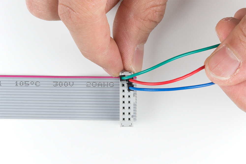
Once you decide what side to connect, start wiring pin 1 by connecting a red wire for R0. Then connect pin 2 by connecting a green wire for G0. After connecting pin 3 using a blue wire for B0, continue wiring the pins based on the hookup table.
To help keep track of what side you are connecting to, feel free to label your connections with a marker.
Connecting the Clock Pin
This is the last pin that has some restriction on where it can go -- it must be connected to one of Arduino's port B pins. That means it must be either 8, 9, 10, 11, 12, or 13. The example code has it defined as pin 11 in the hookup table. Make sure to check your pin definition for the clock as it may vary with the code you are using.
Connecting to A, B, C, (D for 32x32 users), OE, and STB Pins
These five (or six if you're using a 32x32 matrix) pins can be plugged in anywhere you may have space on your Arduino. Although, there's probably not a lot of room left... We chose to stick A, B, and C in pins A0, A1, and A2 respectively. OE connects to pin 9. STB to pin 10. And, if you're using a 32x32 matrix, D goes to A3 as stated in the hookup table.
Feel free to swap those up if your application requires. Just make sure you switch it up in the example code too.
Connecting to Ground(s) Pins
Last, but certainly not least (well, maybe, if we're talking about potential) is ground. There are three unlabeled pins on the connector which should all be tied to ground.
If you don't have anything else plugged into them, there should be three ground pins available on your Arduino. If you're struggling to find ground pins, though, you should be able to get away with only plugging one of the ground pins to your Arduino. Woo color coded wires!
Power
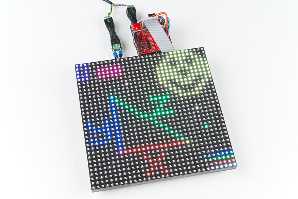
Once you are finished connecting the LED panel to an Arduino, add your 5V power supply to the panel's power connector. Don't forget to add power to your Arduino!
 |
 |
| 16x32 Fully Connected to the RedBoard | 32x32 Fully Connected to the Arduino Mega 2560 |
Connecting to 32x64 RGB LED Panels
For anyone connecting to the 32x64 RGB Panels, you will need to use an Arduino Mega 2560 with the library. Otherwise, the panels will not be able to display as expected due to the limitations of the library and the Arduino Uno.
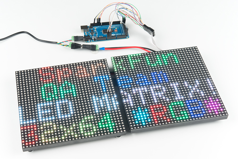
To daisy chain two 32x32 RGB matrices together, connect another IDC cable from the output of the first panel to the input of the second panel. Then connect the second 4-pin polarized connector to the input power connector. After modifying the test_shapes_32x64.ino, the display will output as a 32x64 matrix as shown below.
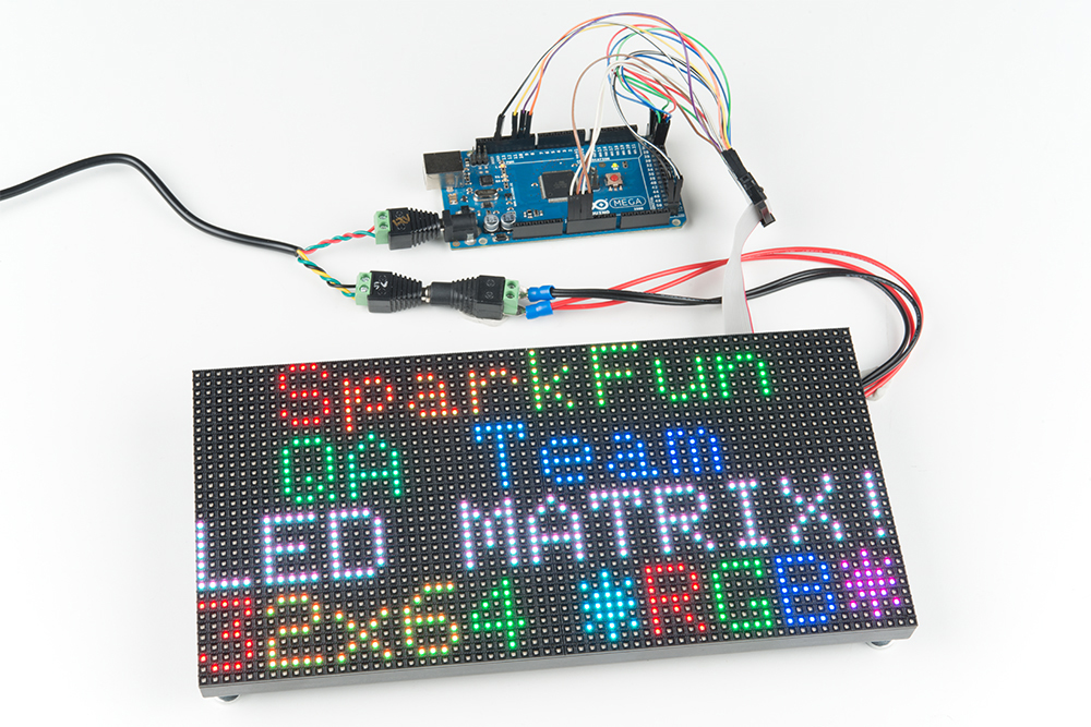
Here's an example with the 32x64 matrix with 4mm pitch.
When using an array higher than 32x64, another library would be a better option with a Teensy 3.0+, FPGA, or Raspberry Pi. You may need to level shift to convert 3.3V to 5V for the RGB LED panel to recognize the I/O signals. For more information, check out the links in the Resources and Going Further.
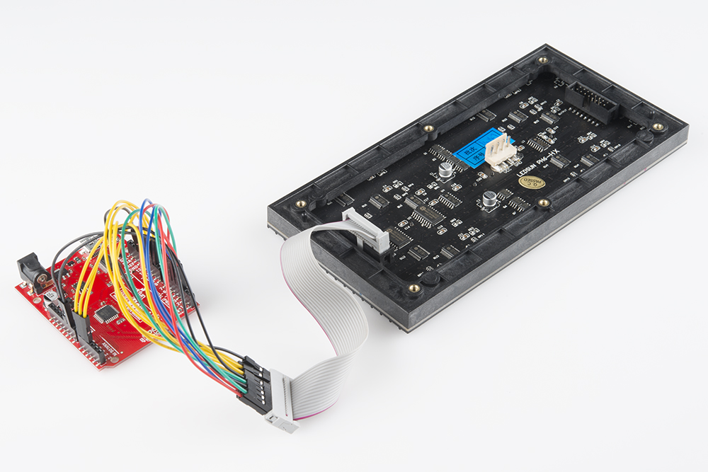
Custom Shield Adapter
If you have a prototyping shield, try making a custom shield adapter for a more secure connection. Here's an example of using an XBee shield's prototyping area with the connection specifically for the RGB LED panels. Follow the steps outlined above but solder the connection together.
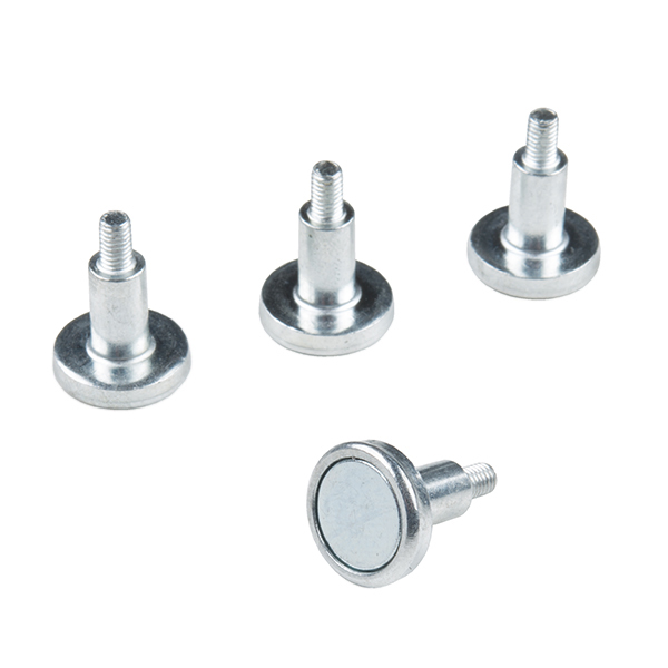
Magnetic Mounts
Depending on the supplier, you may receive a set of magnetic mounts. Add it to the panel's mounting holes to stick on a fridge or metal wall! They also work great as a standoff. Just make sure to secure and insulate your wires to prevent any shorts if there is metal behind the panel.