RedBoard Plus Hookup Guide
 bboyho, santaimpersonator
Hardware Assembly
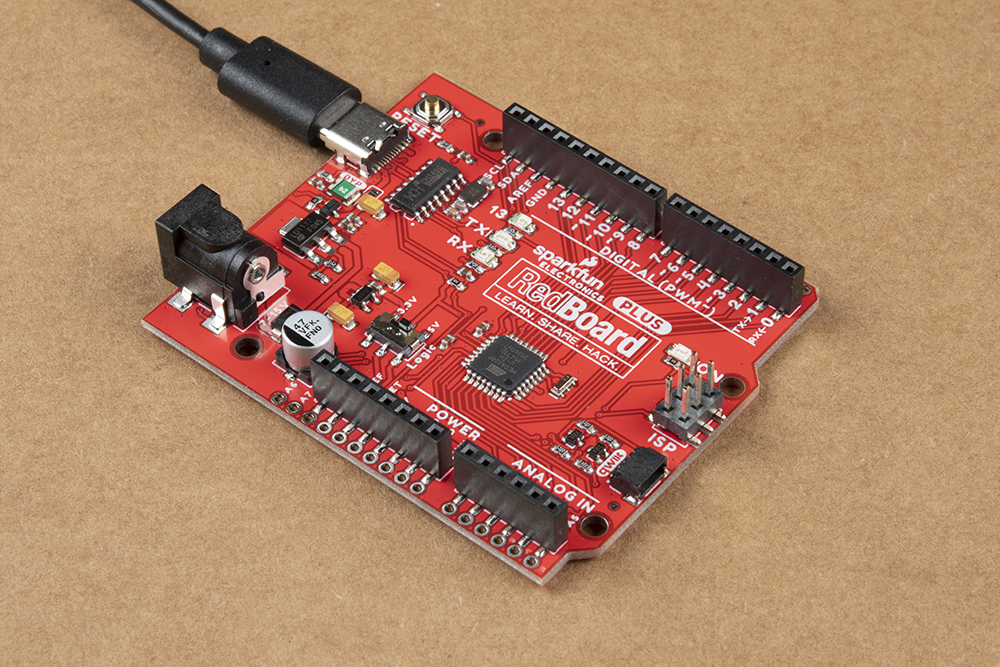
To power and program the board, all you need is a USB C cable. Hold down on the connector with your index finger and thumb on one hand. Using your other hand's index finger and thumb, insert the USB cable into the connector.
At a minimum, your board should look like the image below.
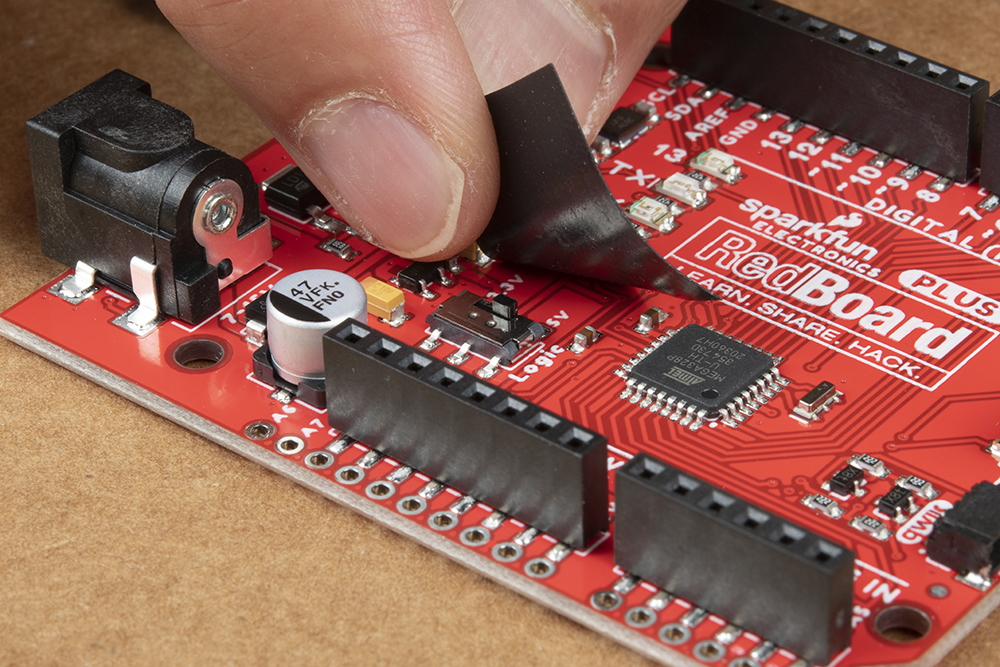
I/O Logic Level Voltage
We recommend having the board set to 5V for the system voltage. Once set, we recommend adding a piece of tape to hold the switch down to avoid accidentally damaging any 3.3V sensitive devices connected to the board or any peripherals expecting 5V logic when prototyping.
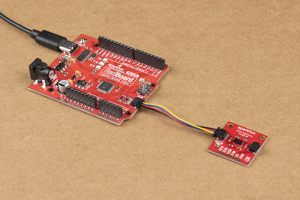
Qwiic Device
If you decide to connect a Qwiic-enabled device to the board, simply plug in a Qwiic cable between the RedBoard Plus and your chosen Qwiic device. The Qwiic connect system makes it easy to add additional functionality to the board. If you're going to be soldering to the through hole pins for I2C functionality, then just attach lines to power, ground, and the I2C data lines on the header pins or PTH pads.
3.3V Power Injection
The 3.3V voltage regulator should provide sufficient power to your Qwiic enabled devices. In special cases, you may need to disconnect the 3.3V line and inject a separate 3.3V regulated voltage down the line if you have several daisy chained Qwiic devices. You can leave the GND line alone, as that ground loops your system, providing a consistent reference voltage for your I2C signals.
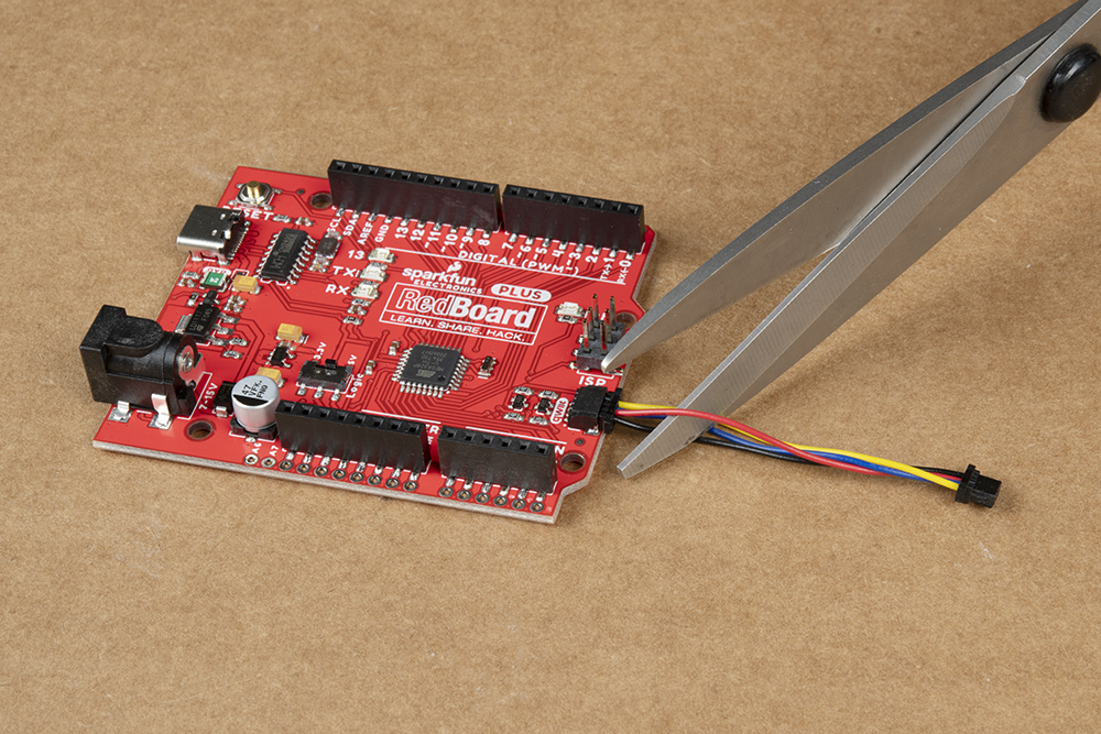
By cutting the 3.3V line, this allows you to power all your devices without straining the 3.3V regulator on the board. Since, all voltage regulators are slightly different and don't maintain a perfect 3.3 voltage, the 3.3V AP2112 regulator would be constantly battling the voltage regulator of your separate power supply to regulate its version of 3.3V. For more details on voltage regulators, check out this According to Pete blog post. Or check out the How to Power a Project: Voltage/Current Considerations for some ideas on adding power to your daisy chained Qwiic devices.
Jumper Wire
All of the pins are broken out to 0.1"-spaced female headers (i.e. connectors) on the outer edges of the board. Additionally, there are PTH pads adjacent to each pin. There are a variety of wires, connectors, and other items that can be inserted into these headers to interface with the Arduino. Jumper wires are a good option if you want to connect the RedBoard Plus up to other pieces of circuitry that may live on a breadboard. Below is an example circuit taken from the SparkFun Inventor's Kit V4.1.
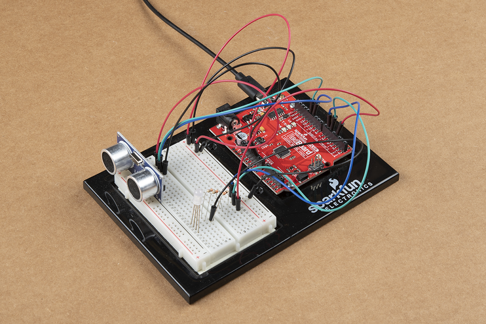
When connecting to the headers, be sure you are aware of the functionality of the pins you are using.
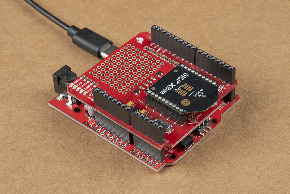
Arduino Shields
Shields are another popular way to interface with the headers. These Arduino-shaped boards are stackable and connect to all four headers of the RedBoard Plus at once. Shields exist in hundreds of forms, they can add GPS, WiFi, MP3 decoding, and all sorts of other functionality to your Arduino. For more details on Arduino shields and shield assembly, please refer to this Arduino Shields tutorial.