RedBoard Edge Hookup Guide
 Englandsaurus
 Introduction
The RedBoard Edge is a nifty little rework of the SparkFun RedBoard designed to be panel mounted in your custom project enclosure to allow for an easy way to make a clean, finished looking product. It has all the features of a normal RedBoard, allowing you to prototype on a RedBoard and easily move your project over to a RedBoard Edge without complication.
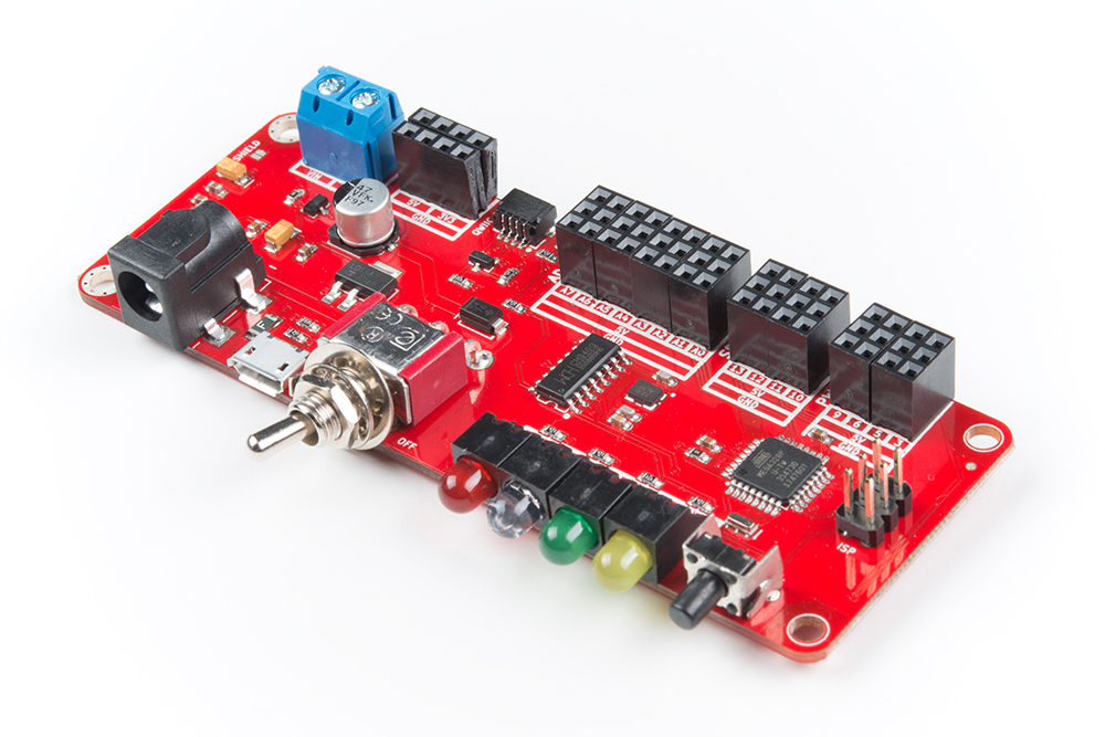
SparkFun RedBoard Edge
DEV-14525The RedBoard Edge is just as easy to use as a regular RedBoard, so it's still an excellent learning platform for physical computing.
The goal of this tutorial is to familiarize you with the RedBoard Edge so you'll be able to easily transfer over your RedBoard project when you're ready to go from a prototype to an enclosed product. Since it's basically a reshaped RedBoard, you may be able to glaze over parts of this tutorial if you're familiar with how the RedBoard works.
Required Materials
To follow along with this tutorial, you will need the following materials. You may not need everything though depending on what you have. Add it to your cart, read through the guide, and adjust the cart as necessary.
You will need a RedBoard Edge and a micro-B-to-A USB cable. The USB interface serves two purposes: it powers the RedBoard Edge and allows you to upload programs to it.


SparkFun RedBoard Edge
DEV-14525You'll also need a computer -- Mac, PC, or Linux will do -- with the Arduino IDE installed on it. You can download Arduino from their website. They've got installation instructions there, but we'll also go over installation in this tutorial.
Tools
Depending on your setup, you may need a soldering iron, solder, and general soldering accessories.


Weller WLC100 Soldering Station
TOL-14228Suggested Reading
The RedBoard Edge aims to be as beginner friendly as a microcontroller platform can be. You can get by using it without an innate knowledge of Ohm's Law or How Electricity Works (but a little understanding wouldn't hurt!). The board utilizes the Qwiic system so we recommend reading here for an overview.
| Qwiic Connect System |
Brushing up on your skills in I2C is also recommended, as all Qwiic sensors are I2C. If you aren’t familiar with the following concepts, we recommend checking out these tutorials before continuing.
What is a Circuit?
What is an Arduino?
I2C
A Rearranged RedBoard
With the RedBoard Edge, we've rearranged the RedBoard Programmed with Arduino to include everything "user-facing" (i.e. "front" side) on one side of the board, and everything "project-facing" on the other side of the board.
 |
 |
| User-Facing Side (i.e. "Front" Side) | Project-Facing Side |
Below are images highlighting where all of the things you've come to know and love on your regular old RedBoard have moved to. Pins have been grouped by function (PWM, ADC, SPI), with power rails for 5V and Ground running parallel to each grouping. There are also 4-pin power rails for 5V and 3.3V right next to the 5mm 2-pin screw terminal which is connected to VIN through the toggle switch on the user-facing side of the board.
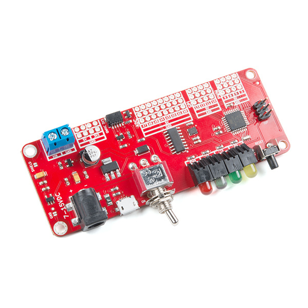
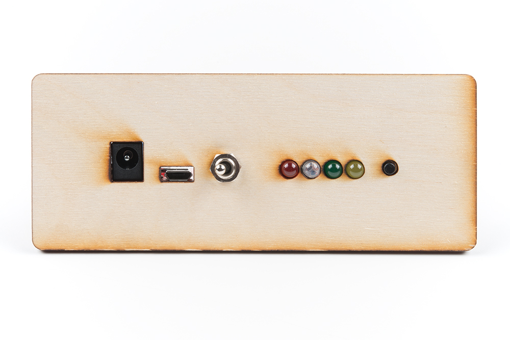
The User-Facing Side (i.e. "Front" Side)
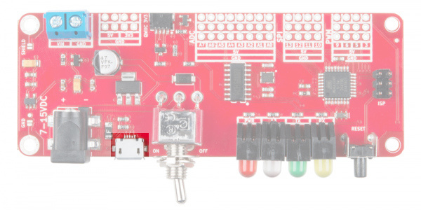
micro-B USB
The RedBoard Edge can be powered via either the USB or barrel jack connectors. If you choose to power it via USB, the other end of the USB cable can be connected to either a computer or a (5V regulated) USB wall charger.
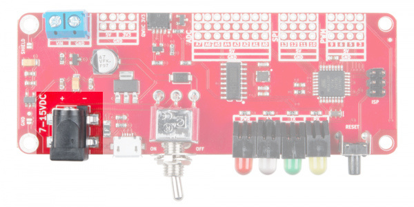
Barrel Jack for VIN
The power jack accepts a center-positive barrel connector with an outer diameter of 5.5mm and inner diameter of 2.1mm. Our 9V and 12V wall adapters are good choices if you're looking to power the RedBoard this way. Any wall adapter connected to this jack should supply a DC voltage between 7V and 15V.
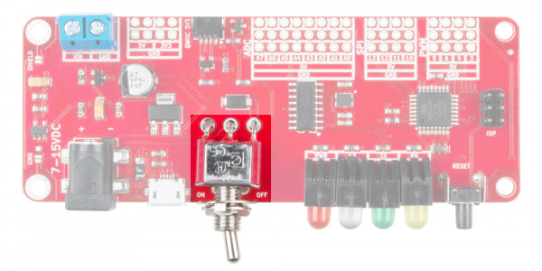
Power Switch
The board has a switch to toggle power for the rest of the board. Note that the toggle switch will not disconnect USB power.
Choosing Power for the RedBoard Edge
There are a few options to power the RedBoard Edge depending on your preference and project needs. USB is usually the easiest way to power the board, especially when you're programming it, because the USB interface is required for uploading code too. Why would you use the barrel jack? Usually, it's because you need more power. A USB port is usually only allowed to supply 500mA. If you need more than that a wall adapter may be your only choice.
It is acceptable to connect both a barrel jack and a USB connector at the same time. The RedBoard Edge has power-control circuitry to automatically select the best power source. As explained earlier, the toggle switch will not disconnect USB power.
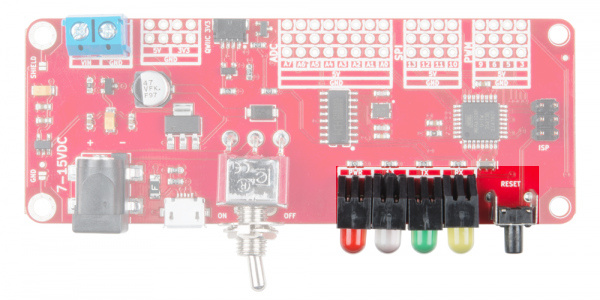
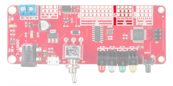
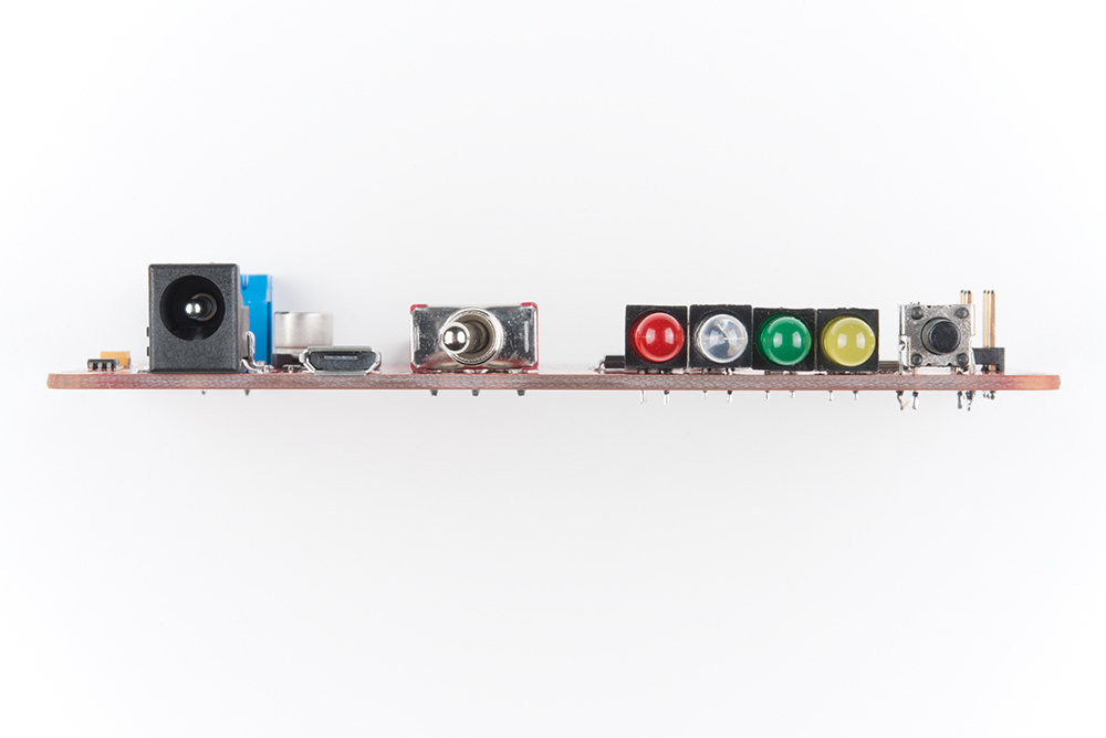
Indication and Interfacing
All of the indication lights have been moved to the front side of the board, so you would be able to see them in your custom enclosure. From left to right, the indicator lights are connected to power, pin 13, TX, and RX, shown in the image below. The button on the far right of the board controls Reset.
The Project-Facing Side
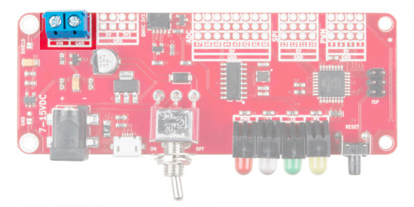
Screw Terminals for VIN
This barrel connector is connected to the screw terminals on the project-facing side of the board through the toggle switch on the front of the board.
PTH Power Pins
The board also comes with 5V, 3.3V, and GND pins throughout the board.
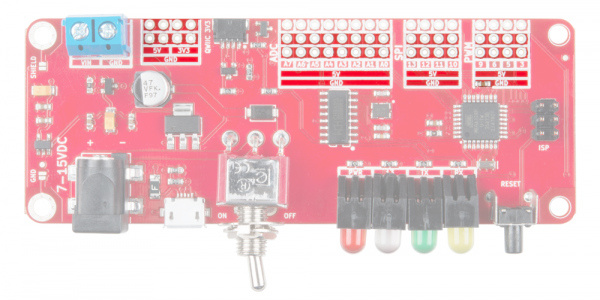
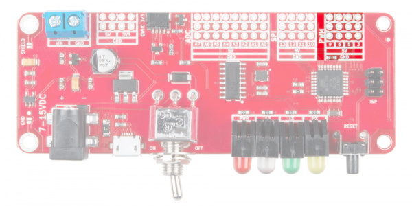
Pin Grouping
The RedBoard Edge has its pins separated into three groups on the project facing side of the board (ADC, SPI, and PWM) which are highlighted in the image below. These pins have the same functions as their RedBoard counterparts so expect to be able to use them like you would on your regular old RedBoard. Each group of three rows has the pins broken out on the top row, a 5V rail in the middle row, and ground on the bottom row.
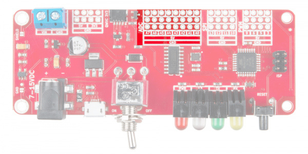
Analog Inputs
There are eight analog inputs on the analog header. These pins all have analog-to-digital converters, which can be used to read in an analog voltage between 0 and 5V. These are useful if you need to read the output of a potentiometer or other analog sensors. Only analog pins A0 through A5 can also serve as digital inputs and outputs.
Serial Peripheral Interface (SPI)
The center group of 4 pins is the SPI Interface where pin 10 = SS, pin 11 = MOSI, pin 12 = MISO and pin 13 = SCK.
Pulse Width Modulation (PWM)
The furthest right grouping of pins are the Pulse-Width Modulation (PWM) pins, which can be used to drive LED's or servos.
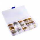
Headers
The RedBoard Edge does not come with headers on-board to allow you the option to be able to solder your finished circuit straight into the board. However, if you'd like to use your Edge for something more along the lines of prototyping purposes, grab some headers.
Check out our through hole soldering tutorial if you have yet to solder headers to a board
Other Neat Features
Grounded Mounting Holes
One of the cool things about the RedBoard Edge is the ability to ground the board to your metal enclosure through the standoffs on the left side. You can choose to connect your enclosure ground to either the USB shield or the board's ground, or both. Simply add solder to the respective jumper pad and connect the enclosure to your board with any 4-40 screw.
 |
 |
| USB Shield GND Mounting Hole | GND Mounting Hole |
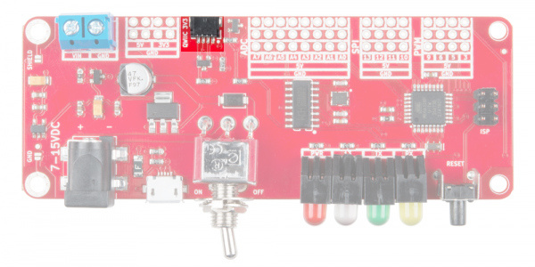
Qwiic Connector
We've also added a Qwiic connector, sandwiched in there between the power and ADC pins, to allow the RedBoard Edge to interface with SparkFun's Qwiic Ecosystem.
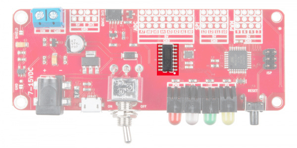
CH340G USB-to-Serial Converter
As opposed to using the FTDI for USB-to-serial conversion, the board uses the CH340G IC. One advantage is that it does not need a driver since most operating systems have the CDC drivers pre-installed. What this means is that you shouldn’t need to install any extra software.
Download/Install Arduino
Before you plug the RedBoard Edge into your computer, you'll need to install Arduino first.
Installing Arduino
To begin, head over to Arduino's download page and grab the most recent, stable release of Arduino. Make sure you grab the version that matches your operating system.
The installation procedure is fairly straightforward, but it varies by OS. Here are some tips to help you along. We've also written a separate Installing Arduino tutorial if you get really stuck.
Installing Arduino IDE
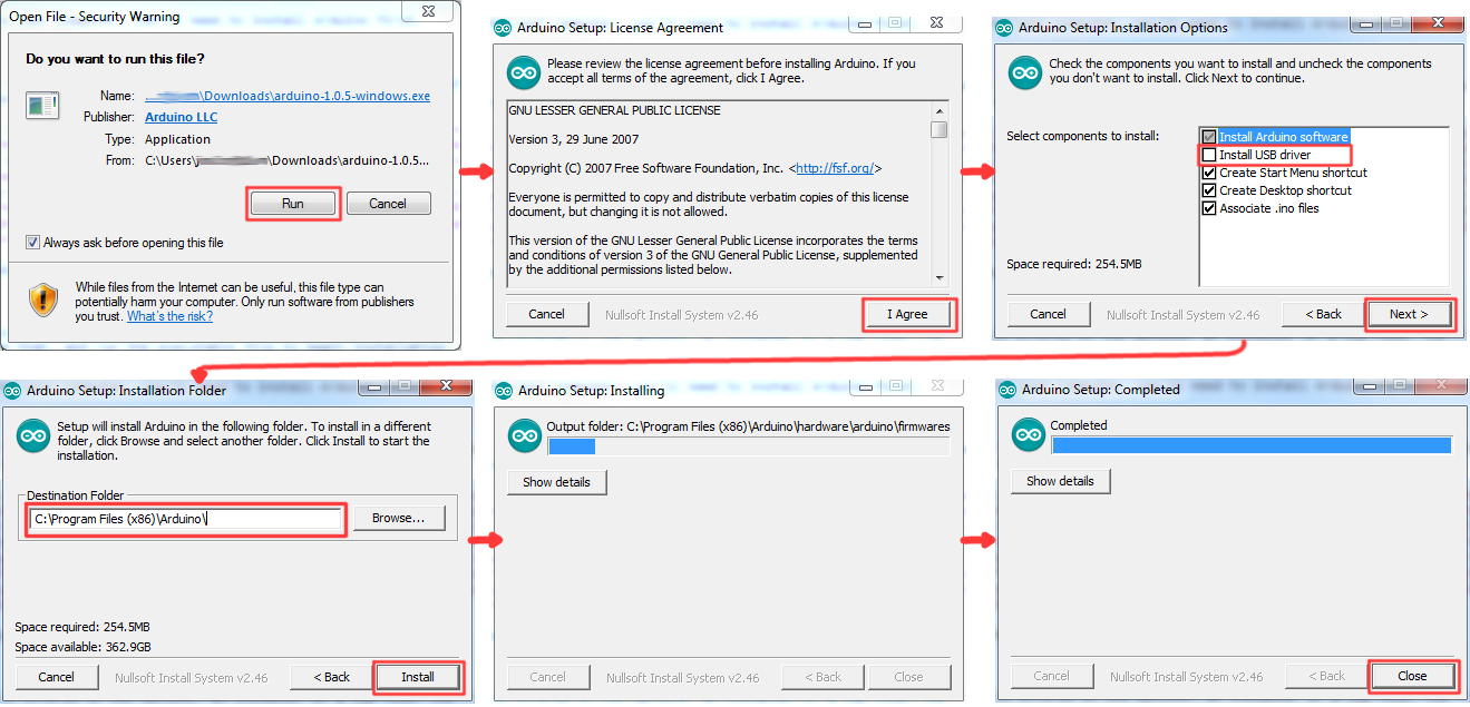
Windows Install Tips
The Windows version of Arduino is offered in two options: an installer or a zip file. The installer is the easier of the two options, just download that, and run the executable file to begin installation. If you're prompted to install a driver during installation, select "Don't Install" (the RedBoard Edge doesn't use the same drivers). Don't forget which directory it installs to (defaults to "Program Files/Arduino").
If, instead, you choose to download the zip file version of Arduino, you'll need to extract the files yourself. Don't forget which folder you extract the files into! We'll need to reference that directory when we install drivers.
Mac Install Tips
The Mac download of Arduino is only offered in a zip file version. After the download is finished, simply double-click the .zip file to unzip it.

Following that, you'll need to copy the Arduino application into your applications folder to complete installation.
Linux Install Tips
As you Linux users are no doubt aware, there are many flavors of Linux out there, each with unique installation routines. Check out the Linux section of the Installing Arduino tutorial for some helpful links for an assortment of Linux distributions.
For Ubuntu and Debian users, installing Arduino should be as easy as running a little "apt-get" magic, with a command like:
language:bash
sudo apt-get update && sudo apt-get install arduino arduino-core
And other Linux distros aren't too dissimilar from that.
With Arduino downloaded and installed, the next step is to plug the RedBoard Edge in and install some drivers! Pretty soon you'll be blinking LEDs, reading buttons, and doing some physical computing!
Drivers (If You Need Them)
The driver should automatically install on most operating systems. However, there is a wide range of operating systems out there. You may need to install drivers the first time you connect the chip to your computer's USB port or when there are operating system updates. For more information, check out our How to Install CH340 Drivers Tutorial.
How to Install CH340 Drivers
Uploading Blink
Note: This example assumes you are using the latest version of the Arduino IDE on your desktop. If this is your first time using Arduino, please review our tutorial on installing the Arduino IDE.
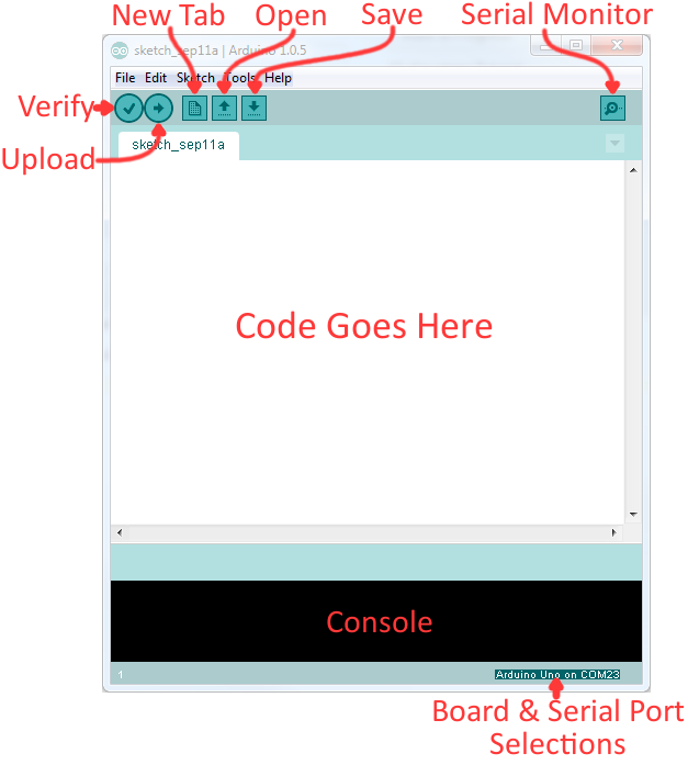
Now it's finally time to open up the Arduino IDE Software. You'll be presented with a window that looks a little something like this:
Lets upload a Blink sketch to make sure our new RedBoard Edge setup is totally functional. Go up to the File menu in Arduino, then go to Examples > 01.Basics > Blink to open it up.
Before we can send the code over to the RedBoard Edge, there are a couple adjustments we need to make.
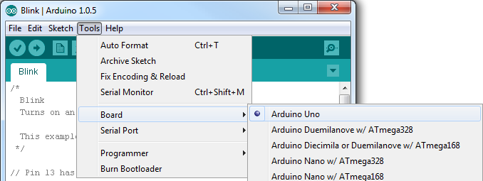
Select a Board
This step is required to tell the Arduino IDE which of the many Arduino boards we have. Go up to the Tools menu. Then hover over Board and make sure Arduino Uno is selected.
Select a Serial Port
Next up we need to tell the Arduino IDE which of our computer's serial ports the RedBoard is connected to. For this, again go up to Tools, then hover over Serial Port and select your RedBoard's COM port.
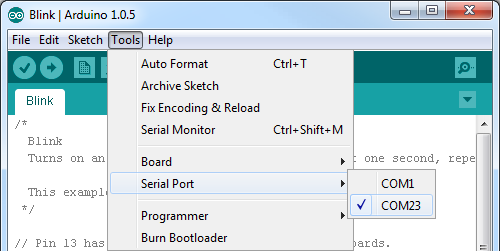
If you've got more than one port, and you're not sure which of the serial ports is your RedBoard Edge, unplug it for a moment and check the menu to see which one disappears.
Upload!
With all of those settings adjusted, you're finally ready to upload some code! Click the Upload button (the right-pointing arrow) and allow the IDE some time to compile and upload your code. It should take around 10-20 seconds for the process to complete. When the code has uploaded, you should see something like this in your console window:
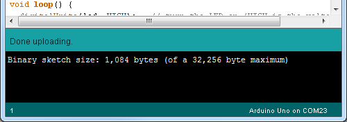
And if you look over to the RedBoard Edge, you should see the blue LED turn on for a second, off for a second, on for a second, off for a second...ad infinitum (at least until it loses power). If you want to adjust the blink speed, try messing with the "1000" value in the delay(1000); lines. You're well on your way to becoming an Arduino programmer!
Something Wrong?
Uh oh! If you didn't get a "Done Uploading" message, and instead got an error, there are a few things we can double-check.
If you got an avrdude: stk500_getsync(): not in sync: resp=0x00 error in your console window.
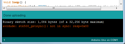
Either your serial port or board may be incorrectly set. Again, make sure Arduino Uno is the board selection (under the "Tools > Board" menu). The serial port is usually the more common culprit here. Is the Serial Port correctly set (under the "Tools > Serial Port" menu)? Did the drivers successfully install? To double check your RedBoard Edge's serial port, look at the menu when the board is plugged in, then unplug it and look for the missing port. If none of the ports are missing, you may need drivers.
Panel Mounting
The RedBoard Edge was designed with panel mounting in mind, so let's look at how everything is laid out on the user-facing side so we can put holes in the proper places for a panel or enclosure.
The RedBoardEdgePanel.svg used for a panel mount should work well with a printer or maybe even a laser cutter. The file can be downloaded from the button below. Just make sure to unzip the file before using.
Once you've created your front panel, it's easy to slide your RedBoard Edge through and secure it in place using the nut on the toggle switch. Look at that, my apartment smells of many burnt electronics and rich mahogany.
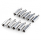
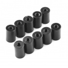
Mounting Hardware
If you'd like to mount the RedBoard Edge to some sort of baseplate as well, you can attach the RedBoard Edge to your baseplate using 4-40 standoffs and screws to attach the RedBoard Edge to your baseplate. Keep in mind that grounding the board through the mounting holes will require metal standoffs.
Resources and Going Further
Now that you've gotten code uploaded to your RedBoard Edge, you're ready to finally create that nice, clean looking panel mounted project of your dreams.
For more on the RedBoard Edge, check out the links below:
- Schematic (PDF)
- KiCad Files (ZIP)
- Software
- Panel Mounting Files (ZIP)
- Qwiic Landing Page
- GitHub Repo
- SFE Product Showcase: SparkFun RedBoard Edge
Need some inspiration for your next project? Check out some of these related tutorials:
Light-Seeking Robot
Clap On Lamp
Qwiic Distance Sensor (VL53L1X, VL53L4CD) Hookup Guide
MicroMod Ethernet Function Board - W5500 Hookup Guide
Or check out this blog post for ideas.