RedBoard Edge Hookup Guide
 Englandsaurus
A Rearranged RedBoard
With the RedBoard Edge, we've rearranged the RedBoard Programmed with Arduino to include everything "user-facing" (i.e. "front" side) on one side of the board, and everything "project-facing" on the other side of the board.
 |
 |
| User-Facing Side (i.e. "Front" Side) | Project-Facing Side |
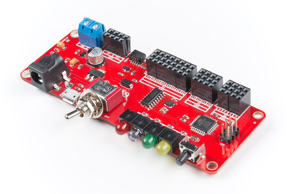
Below are images highlighting where all of the things you've come to know and love on your regular old RedBoard have moved to. Pins have been grouped by function (PWM, ADC, SPI), with power rails for 5V and Ground running parallel to each grouping. There are also 4-pin power rails for 5V and 3.3V right next to the 5mm 2-pin screw terminal which is connected to VIN through the toggle switch on the user-facing side of the board.
The User-Facing Side (i.e. "Front" Side)
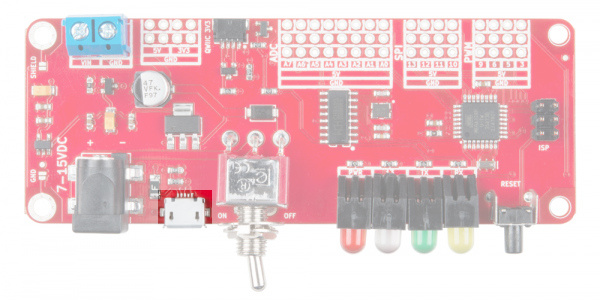
micro-B USB
The RedBoard Edge can be powered via either the USB or barrel jack connectors. If you choose to power it via USB, the other end of the USB cable can be connected to either a computer or a (5V regulated) USB wall charger.
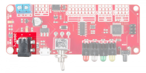
Barrel Jack for VIN
The power jack accepts a center-positive barrel connector with an outer diameter of 5.5mm and inner diameter of 2.1mm. Our 9V and 12V wall adapters are good choices if you're looking to power the RedBoard this way. Any wall adapter connected to this jack should supply a DC voltage between 7V and 15V.
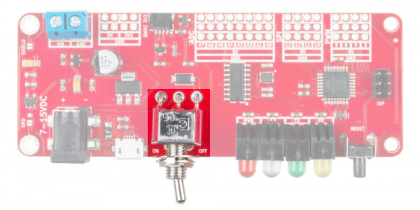
Power Switch
The board has a switch to toggle power for the rest of the board. Note that the toggle switch will not disconnect USB power.
Choosing Power for the RedBoard Edge
There are a few options to power the RedBoard Edge depending on your preference and project needs. USB is usually the easiest way to power the board, especially when you're programming it, because the USB interface is required for uploading code too. Why would you use the barrel jack? Usually, it's because you need more power. A USB port is usually only allowed to supply 500mA. If you need more than that a wall adapter may be your only choice.
It is acceptable to connect both a barrel jack and a USB connector at the same time. The RedBoard Edge has power-control circuitry to automatically select the best power source. As explained earlier, the toggle switch will not disconnect USB power.
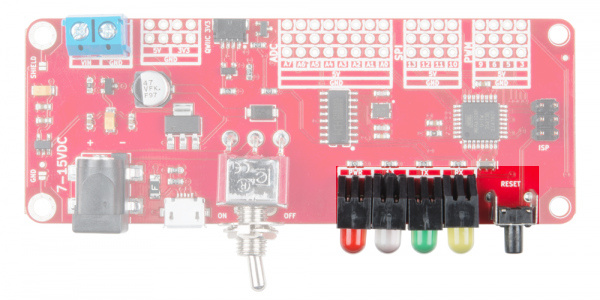
Indication and Interfacing
All of the indication lights have been moved to the front side of the board, so you would be able to see them in your custom enclosure. From left to right, the indicator lights are connected to power, pin 13, TX, and RX, shown in the image below. The button on the far right of the board controls Reset.
The Project-Facing Side
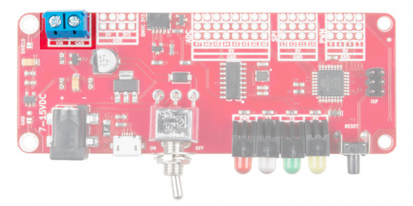
Screw Terminals for VIN
This barrel connector is connected to the screw terminals on the project-facing side of the board through the toggle switch on the front of the board.
PTH Power Pins
The board also comes with 5V, 3.3V, and GND pins throughout the board.
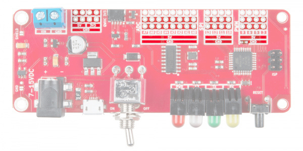
Pin Grouping
The RedBoard Edge has its pins separated into three groups on the project facing side of the board (ADC, SPI, and PWM) which are highlighted in the image below. These pins have the same functions as their RedBoard counterparts so expect to be able to use them like you would on your regular old RedBoard. Each group of three rows has the pins broken out on the top row, a 5V rail in the middle row, and ground on the bottom row.
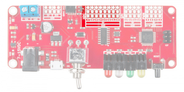
Analog Inputs
There are eight analog inputs on the analog header. These pins all have analog-to-digital converters, which can be used to read in an analog voltage between 0 and 5V. These are useful if you need to read the output of a potentiometer or other analog sensors. Only analog pins A0 through A5 can also serve as digital inputs and outputs.
Serial Peripheral Interface (SPI)
The center group of 4 pins is the SPI Interface where pin 10 = SS, pin 11 = MOSI, pin 12 = MISO and pin 13 = SCK.
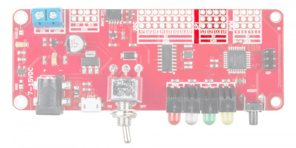
Pulse Width Modulation (PWM)
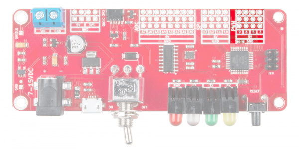
The furthest right grouping of pins are the Pulse-Width Modulation (PWM) pins, which can be used to drive LED's or servos.
Headers
The RedBoard Edge does not come with headers on-board to allow you the option to be able to solder your finished circuit straight into the board. However, if you'd like to use your Edge for something more along the lines of prototyping purposes, grab some headers.
Check out our through hole soldering tutorial if you have yet to solder headers to a board
Other Neat Features
Grounded Mounting Holes
One of the cool things about the RedBoard Edge is the ability to ground the board to your metal enclosure through the standoffs on the left side. You can choose to connect your enclosure ground to either the USB shield or the board's ground, or both. Simply add solder to the respective jumper pad and connect the enclosure to your board with any 4-40 screw.
 |
 |
| USB Shield GND Mounting Hole | GND Mounting Hole |
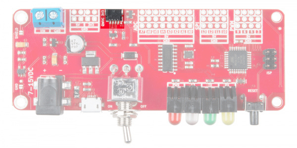
Qwiic Connector
We've also added a Qwiic connector, sandwiched in there between the power and ADC pins, to allow the RedBoard Edge to interface with SparkFun's Qwiic Ecosystem.
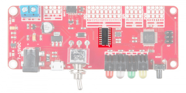
CH340G USB-to-Serial Converter
As opposed to using the FTDI for USB-to-serial conversion, the board uses the CH340G IC. One advantage is that it does not need a driver since most operating systems have the CDC drivers pre-installed. What this means is that you shouldn’t need to install any extra software.