Red Hat Co.Lab Conversation Machine Kit Experiment Guide
 D___Run___
Part 1: Breadboarding, Push Buttons, and LEDs
Here's a walkthrough showing the steps of Part 1.
What is a circuit?
A circuit is a closed loop that electricity can travel around. At its most basic, a circuit consists of three parts:
- A voltage source: The power for the circuit
- A load: The thing that is being powered, like a motor, buzzer, or light
- The circuit path: The continuous path that the current follows as it travels around the circuit
An example of a simple circuit would be a power source (like a battery), a load (like an LED), and the circuit path (the wires that connect them).
Making the Circuit
1. The Power/Voltage Source
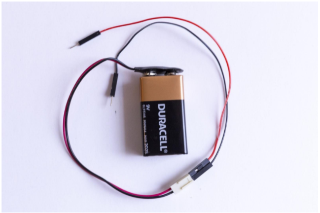
Your kit comes with either four AA batteries and a battery holder, or a 9v battery and 9V snap connector. Each of these are a power/voltage source.
Either the battery pack or the snap connector will have a plastic connector—the small, white, rectangular box at the end of the red and black wires. This makes it easy to connect to many types of electronics; however, we won’t be using it for our project today. The way we will connect the power to the breadboard is actually with jumper wires. Jumper wires are short in length and make connecting components quick and easy.
The jumper wires that come in your kit have small metal pins on either side. The colors of the jumper wires don’t correspond to anything in your kit. Use any two colors that you prefer.
2. The Load
For this circuit, we are going to use a push button switch to trigger an LED. Let’s pause and take a look at what each of these parts actually do.
A switch is a component which controls the “openness” or “closedness” of an electric circuit. They allow control over current flow in a circuit (without having to actually get in there and manually cut or splice the wires). Switches are critical components in any circuit which require user interaction or control.
A switch can only exist in one of two states: Open or closed. In the off state, a switch looks like an open gap in the circuit. This, in effect, looks like an open circuit, preventing current from flowing. In the on state, a switch acts just like a piece of perfectly-conducting wire.
You’ll notice that the tactile push button switches that we are using have 4 pins. The directions below direct you to line up the four pins on the breadboard coordinates before you apply pressure to insert the pins. This ensures the pins are placed in the appropriate locations.
LEDs (that's "ell-ee-dees") are a particular type of diode that convert electrical energy into light. In fact, LED stands for "Light Emitting Diode." In short, LEDs are like tiny lightbulbs. However, LEDs require a lot less power to light up by comparison. They're also more energy efficient, so they don't tend to get hot like conventional light bulbs do (unless you're really pumping power into them). This makes them ideal for mobile devices and other low-power applications.
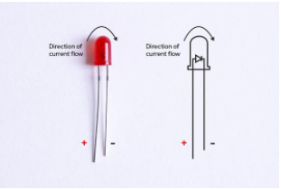
LEDs are polarized which means they can only be connected to a circuit in one direction (if you want them to work, that is!). They're also called directional components, and you can think of them like the turnstile that you might go through at an airport or bus station—it only turns in one direction.
In an LED, the longer leg is the positive (+) connection (or anode) and the shorter leg is the negative (-) connection (or cathode). Current must enter the LED via the cathode (+) and exit via the anode (-). The turnstile only works in that direction.
My way of remembering which leg is positive is to think about the fact that drawing a plus symbol (+) takes twice as much "line" to draw as a minus symbol (-), so the (+) leg has to be longer than the (-) one.
3. The Circuit Path
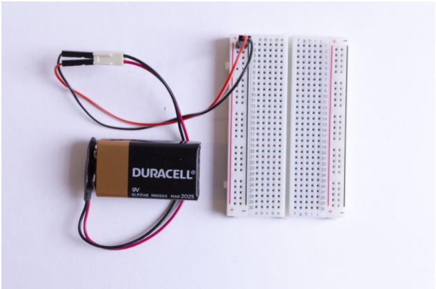
For a circuit to work, the path of the power can’t be interrupted—all pieces have to be in contact. Luckily, we have a breadboard which is a helpful tool we can use to quickly plug in items and keep them connected. It also lets us create, fix small mistakes, and practice with the components. What is a breadboard?
Let’s start by taking a look at the breadboard that is included in your kit: First, notice there are two long columns of holes running down each side of the board, one with a red line beside it, and one with a black line. These are called the power rails and all of the holes in a single power rail are connected to each other. If power is connected to one hole in the column, it's connected to all the other holes in the column.
There are two holes in the plastic molding at the end of the wires coming from the battery pack. Insert a jumper wire into each of these holes and insert the other ends into the (+) power rail and the (-) power rail.
Second, all the holes in a numbered row are connected to each other, but this connection is broken at the small trench or indent that runs down the center of the board. Each side COULD be its own separate circuit. Our project will jump over the trench using jumper wires and send power back and forth.
Basically, you can view a breadboard as a series of columns (labeled A-E and F-J) and rows (labeled 1-30.) And remember, the divide in the middle means A5 isn’t connected to F5. When we get to the instructions down below, we will use this row and column system to mark where connections should be made (A6, E3, H23, etc.).
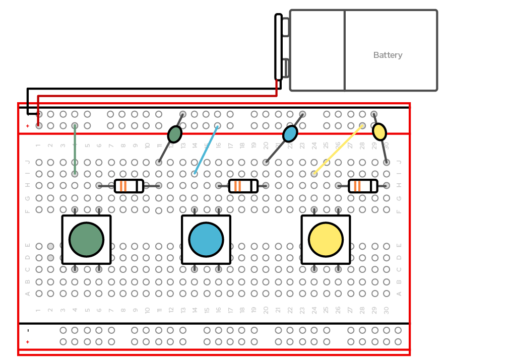
We are going to replicate this circuit (the steps are below).
Create your circuit as follows:
- Place the first push button so that the pins align with C4, C6, F4, and F6. Gently press into place.
- Connect a jumper wire from I4 to positive power (+) rail 4.
- Connect the resistor from H6 to H11.
- Remembering that our LEDs are polarized, place the longer leg into J11 and the shorter into negative power rail (-) 11.
- Place the second push button so that the pins align with C14, C16, F14, and F16. Gently press into place.
- Connect a jumper wire from I14 to positive power (+) rail 14.
- Connect the resistor from H16 to H20.
- Remembering that our LEDs are polarized, place the longer leg into J20 and the shorter into negative power rail (-) 20.
- Place the third push button so that the pins align with C24, C26, F24, and F26. Gently press into place.
- Connect a jumper wire from I24 to positive power (+) rail 24.
- Connect the resistor from H26 to H30.
- Remembering that our LEDs are polarized, place the longer leg into J30 and the shorter into negative power rail (-) 30.
- Connect the jumper wire attached to the positive part of the battery pack terminal to the positive (+) power rail 1 on the right.
- Connect the jumper wire attached to the negative part of the battery pack terminal to the negative (-) power rail 1 on the left.