Red Box Robot Hookup Guide
 Nick Poole
Redbox Robot
Here at SparkFun, we get a lot of compliments on our red boxes. They're strong, stylish and hard to lose on a messy workbench. But, did you know that they also make pretty great robots? Okay, you can make a robot out of almost any box, but it won't be as stylish. This kit has everything you need to transform your favorite cardboard box into a robotic buddy!
Cyber Monday Redbox Robot
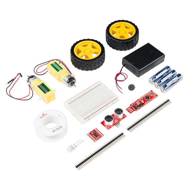
KIT-14062Kit Includes:
- SparkFun RedStick
- SparkFun Motor Driver -- Dual TB6612FNG (1A)
- Hook-up Wire -- White (22 AWG)
- Breadboard -- Self-Adhesive (White)
- 2x Break Away Headers -- Straight
- 3x 1500 mAh Alkaline Battery -- AA
- Battery Holder 3xAA with Cover and Switch
- Mini Speaker -- PC Mount 12mm 2.048kHz
- Ultrasonic Sensor -- HC-SR04
- Hobby Gearmotor -- 200 RPM (Pair)
- Wheel -- 65mm (Rubber Tire, Pair)
- Super Bright LED -- Red 10mm
- Double-Sided Tape (to attach motors to the box)
Covered in This Tutorial
This tutorial will guide you through the assembly, wiring and programming of an obstacle-avoiding robot. You will need to have some basic soldering experience, and you'll need to cut a few holes in a cardboard box. Beyond that, you shouldn't need any special tools or technical skill.
Materials Required
Besides the parts included in your kit, you'll need to following tools:
- Soldering tools, including an iron and solder
- Scissors or a hobby knife
- Wire Strippers
- Googly eyes and other adornments (optional)
Suggested Reading
How to Solder: Through-Hole Soldering
Motors and Selecting the Right One
RedStick Hookup Guide
TB6612FNG Hookup Guide
Building the Chassis
Before we can start to wire our robot, we'll need to assemble the mechanical parts. Luckily, this robot is about as simple as it gets!
Empty out the box in which your kit came. That box is going to become the body for our robot. The included breadboard has a peel-and-stick backing, so let's start by sticking that to the topside of the box, along the hinged side of the box, near the center. In order to connect the rest of the parts, you'll need the strip of double-sided tape that came in your kit. Cut off about an inch of that tape, and use it to stick down the battery pack just below the breadboard, as pictured in the diagram below. Don't worry about the parts stuck into the breadboard just yet. We'll get to that after the mechanical portion is assembled.
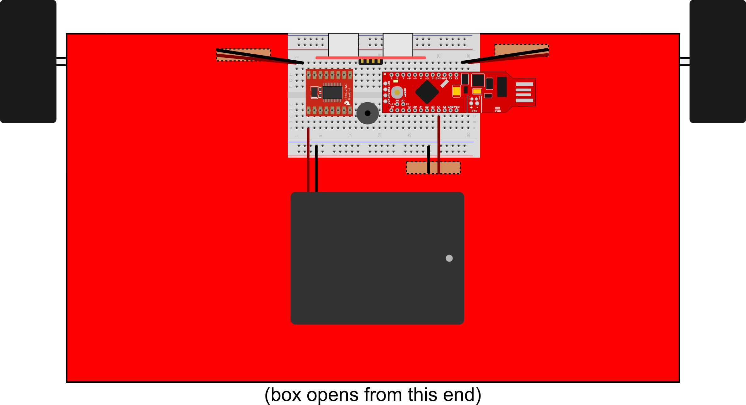
As you can see, there are a few places where it is suggested you cut a hole into the box so wires can be fed through. One hole that you can't see is underneath the battery case so you can access the power switch on the underside. Otherwise, you could just turn it to "ON" and leave it there. Two other such holes are found on the bottom of the box where we're going to attach the motors.
If you look at the hobby motors in the kit, you'll notice that there is an axle running through them so that a wheel can be pressed onto either side. You'll also notice that the wires are gathered on one side of the motor. It'll be easiest to wire the motors if you make sure that they're attached with the wires pointing in toward the middle of the box. Use the remaining length of double-sided tape to mount the motors on the bottom side, front corners of the box. Check out the diagram below for an idea of how it should look.

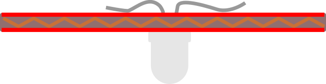
As there are only two motors on this robot, we'll need to add something on the backside to keep it from just dragging around. In this case, we're going to use a 10mm LED as a caster. Not only is this a nice, cheap way to keep your robot's backside off the ground, but it'll also allow us to add cool lighting effects! You shouldn't need to glue the LED into place; just poke it through the cardboard and splay the legs out as pictured below. Later, we'll solder a few wires to this LED, and that should hold it in place.
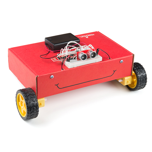
Once you have all the essentials taped into place, you can add some fun decoration to give your robot a little personality. Below, you can see that I've glued down a pair of googly eyes and drawn on a derpy smile with a magic marker.
Wiring the Motors
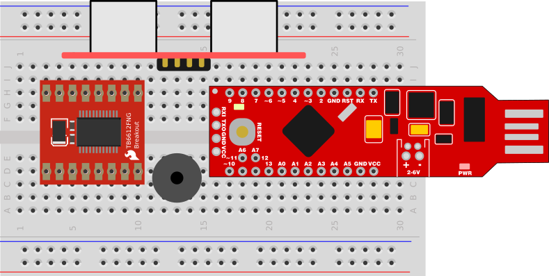
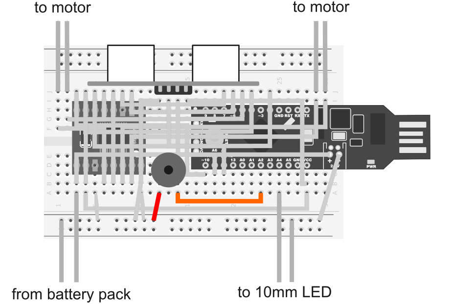
Now that our robot friend has a body (and maybe even a face) it's time to start wiring things together. To ease assembly, we'll be jumping everything together on a breadboard. Before we can do that, though, you'll need to solder headers to the RedStick and the Motor Driver Board. I won't cover that process here; if you're just getting started with soldering, then check out this tutorial. Once everything has headers attached, press the parts into your breadboard as pictured below. Pay close attention to how many rows are free on either side of the breadboard; you'll need them for the motor connections.
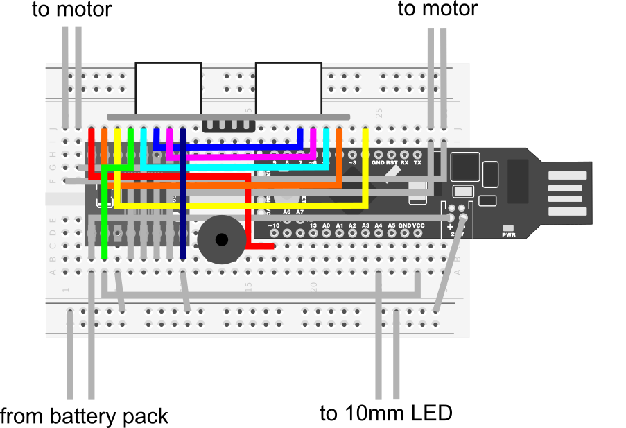
Now that everything is in place, let's add jumper wires to complete our circuit. There's a spool of solid core wire included in your kit, which you'll cut into short lengths and strip on either end. We're going to make a lot of connections here, so the diagram might get messy. To make things easier to follow, I've broken it into stages. In case following a diagram isn't your flavor, I've put together a table that outlines all of the connections. You can find it at the end of this section.
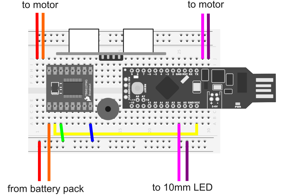
A quick note about the connections above: the motors and battery pack come with wire leads attached, which you should be able to press directly into the breadboard without having to add your own wire.
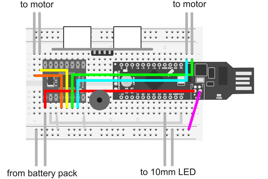
Notice in the diagram above that there are two wires connected to the battery terminals on the RedStick. You may be tempted to connect these wires to VCC and GND instead, but don't do it! The battery connector actually passes through a booster circuit, so as your batteries drain, the RedStick won't power down prematurely.
| Motor Driver Pin | RedStick Pin | Other |
| VM | Battery + | Battery Pack + |
| VCC | VCC | |
| GND | GND | Battery Pack - |
| A01 | Left Motor + | |
| A02 | Left Motor - | |
| B01 | Right Motor + | |
| B02 | Right Motor - | |
| PWMA | 10 | |
| AIN2 | 4 | |
| AIN1 | 2 | |
| STBY | Any VCC connection | |
| BIN1 | 5 | |
| BIN2 | 7 | |
| PWMB | 6 | |
| A4 | 10mm LED Anode | |
| GND | 10mm LED Cathode |
Making Moves
Now that you've made all of the connections you need to get the motors running, let's get some code on that RedStick to spin our wheels! I'm going to assume for the purposes of this section that you have some experience with Arduino programming and that you're already set up to load code onto the SparkFun RedStick. If you need a little help getting started, check out this tutorial.
In order to get code onto your RedStick, you will need to either remove it from the breadboard (carefully) or use a USB extension cable to plug it into your computer's USB port.
The Arduino code below takes advantage of our library. If you are unfamiliar with installing an Arduino library, check out our tutorial.
Download the library using the link below, or grab the latest version from our GitHub repository.
This example code will make your robot do a little dance. This is a great way to make sure you've wired everything right so far. Besides, we've been staring at this thing long enough; it's about time it did something!
language:c
/******************************************************************
TestRun.ino
TB6612FNG H-Bridge Motor Driver Example code
Michelle @ SparkFun Electronics
8/20/16
https://github.com/sparkfun/SparkFun_TB6612FNG_Arduino_Library

Uses 2 motors to show examples of the functions in the library.  This
causes a robot to do a little 'jig'.  Each movement has an equal and
opposite movement so assuming your motors are balanced the bot should
end up at the same place it started.

Resources:
TB6612 SparkFun Library
*****************************************************************/

// This is the library for the TB6612 that contains the class Motor and all the
// functions
#include <SparkFun_TB6612.h>

// Pins for all inputs, keep in mind the PWM defines must be on PWM pins
// the default pins listed are the ones used on the Redbot (ROB-12097) with
// the exception of STBY which the Redbot controls with a physical switch
#define AIN1 2
#define BIN1 7
#define AIN2 4
#define BIN2 5
#define PWMA 10
#define PWMB 6
#define STBY 9

// these constants are used to allow you to make your motor configuration
// line up with function names like forward.  Value can be 1 or -1
const int offsetA = -1;
const int offsetB = -1;

// Initializing motors.  The library will allow you to initialize as many
// motors as you have memory for.  If you are using functions like forward
// that take 2 motors as arguements you can either write new functions or
// call the function more than once.
Motor motor1 = Motor(AIN1, AIN2, PWMA, offsetA, STBY);
Motor motor2 = Motor(BIN1, BIN2, PWMB, offsetB, STBY);

void setup()
{
 //Nothing here
}


void loop()
{
   //Use of the drive function which takes as arguements the speed
   //and optional duration.  A negative speed will cause it to go
   //backwards.  Speed can be from -255 to 255.  Also use of the
   //brake function which takes no arguements.
   motor1.drive(255,1000);
   motor1.drive(-255,1000);
   motor1.brake();
   delay(1000);

   //Use of the drive function which takes as arguements the speed
   //and optional duration.  A negative speed will cause it to go
   //backwards.  Speed can be from -255 to 255.  Also use of the
   //brake function which takes no arguements.
   motor2.drive(255,1000);
   motor2.drive(-255,1000);
   motor2.brake();
   delay(1000);

   //Use of the forward function, which takes as arguements two motors
   //and optionally a speed.  If a negative number is used for speed
   //it will go backwards
   forward(motor1, motor2, 150);
   delay(1000);

   //Use of the back function, which takes as arguments two motors
   //and optionally a speed.  Either a positive number or a negative
   //number for speed will cause it to go backwards
   back(motor1, motor2, -150);
   delay(1000);

   //Use of the brake function which takes as arguments two motors.
   //Note that functions do not stop motors on their own.
   brake(motor1, motor2);
   delay(1000);

   //Use of the left and right functions which take as arguements two
   //motors and a speed.  This function turns both motors to move in
   //the appropriate direction.  For turning a single motor use drive.
   left(motor1, motor2, 100);
   delay(1000);
   right(motor1, motor2, 100);
   delay(1000);

   //Use of brake again.
   brake(motor1, motor2);
   delay(1000);

}
With this code compiled and running on your robot, you've made the first step toward bringing your red box to life. You've probably noticed, however, that it's a little clumsy. It just runs right into anything in its path! The next thing we're going to do is give it the ability to avoid those obstacles...
Avoiding Obstacles
Before we upload fresh code to take advantage of our robot's ultrasonic sensor, we'll need to wire the sensor to the RedStick. This sensor only requires four wires to work, and I've highlighted them in the diagram below.

Once you've added these wires, it's just a matter of uploading the example code below:
language:c
#include <SparkFun_TB6612.h>

// these constants are used to allow you to make your motor configuration
// line up with function names like forward.  Value can be 1 or -1
const int offsetA = -1;
const int offsetB = -1;

// Pins for all inputs, keep in mind the PWM defines must be on PWM pins
// the default pins listed are the ones used on the Redbot (ROB-12097) with
// the exception of STBY which the Redbot controls with a physical switch
#define AIN1 2
#define BIN1 7
#define AIN2 4
#define BIN2 5
#define PWMA 10
#define PWMB 6
#define STBY 9

// Initializing motors.  The library will allow you to initialize as many
// motors as you have memory for.  If you are using functions like forward
// that take 2 motors as arguements you can either write new functions or
// call the function more than once.
Motor motor1 = Motor(AIN1, AIN2, PWMA, offsetA, STBY);
Motor motor2 = Motor(BIN1, BIN2, PWMB, offsetB, STBY);

// Pins
const int TRIG_PIN = 11;
const int ECHO_PIN = 12;

// Anything over 400 cm (23200 us pulse) is "out of range"
const unsigned int MAX_DIST = 23200;

void setup() {

  // Setup all of our pins
  pinMode(TRIG_PIN, OUTPUT);
  digitalWrite(TRIG_PIN, LOW);
  pinMode(2, OUTPUT); digitalWrite(2, LOW);
  pinMode(4, OUTPUT); digitalWrite(4, LOW);
  pinMode(5, OUTPUT); digitalWrite(5, LOW);
  pinMode(7, OUTPUT); digitalWrite(7, LOW);
  pinMode(3, OUTPUT);
  pinMode(6, OUTPUT);
  pinMode(A4, OUTPUT);
  digitalWrite(A4, HIGH);

}

void loop() {

  // Start moving forward
  forward(motor1, motor2, 200);

  unsigned long t1;
  unsigned long t2;
  unsigned long pulse_width;
  float cm;

  // Hold the trigger pin high for at least 10 us
  digitalWrite(TRIG_PIN, HIGH);
  delayMicroseconds(10);
  digitalWrite(TRIG_PIN, LOW);

  // Wait for pulse on echo pin
  while ( digitalRead(ECHO_PIN) == 0 );

  // Measure how long the echo pin was held high (pulse width)
  // Note: the micros() counter will overflow after ~70 min
  t1 = micros();
  while ( digitalRead(ECHO_PIN) == 1);
  t2 = micros();
  pulse_width = t2 - t1;

  // Calculate distance in centimeters.
  cm = pulse_width / 58.0;

  // If an obstacle is detected fewer than 20 centimeters away,
  // run the motors backwards and then coin flip to decide which
  // way to turn before continuing on.
  if(cm<20){back(motor1, motor2, 250); delay(1000);
  if(flip()){left(motor1, motor2, 250);}else{right(motor1, motor2, 250);}
  delay(2500);}

  // Wait at least 60ms before next measurement
  delay(60);
}

// Coinflip function that randomly returns a 1 or 0
bool flip(){

  static uint32_t buf = 0;
  static uint8_t idx = 0;
  if (idx)
  {
    buf >>= 1;
    idx--;
  }
  else
  {
    buf = random();  // refill
    idx = 30;
  }
  return buf & 0x01;

}
If everything is working correctly, your robot should be dodging obstacles. More specifically, if an object comes within 20 centimeters of the front of the robot, the robot will reverse direction and turn randomly before continuing on its way. This is a nice self-preservation instinct for a robot to have. However, if science fiction movies have taught me anything, a small robot needs a cute voice to survive.
The Voice
There's one more quick connection we'll need to make before your robot can whistle. Wire one side of the mini speaker to the A4 pin on the RedStick and wire the other side to ground as illustrated below.
The final update that we're going to make to our code today is to add a fun little function I call "Whistle," which picks nine random frequencies and beeps them out in quick succession to approximate a sort of wordless interjection. It doesn't sound like much, but it adds a lot of personality.
language:c
#include <SparkFun_TB6612.h>

// these constants are used to allow you to make your motor configuration
// line up with function names like forward.  Value can be 1 or -1
const int offsetA = -1;
const int offsetB = -1;

// Pins for all inputs, keep in mind the PWM defines must be on PWM pins
// the default pins listed are the ones used on the Redbot (ROB-12097) with
// the exception of STBY which the Redbot controls with a physical switch
#define AIN1 2
#define BIN1 7
#define AIN2 4
#define BIN2 5
#define PWMA 10
#define PWMB 6
#define STBY 9

// Initializing motors.  The library will allow you to initialize as many
// motors as you have memory for.  If you are using functions like forward
// that take 2 motors as arguements you can either write new functions or
// call the function more than once.
Motor motor1 = Motor(AIN1, AIN2, PWMA, offsetA, STBY);
Motor motor2 = Motor(BIN1, BIN2, PWMB, offsetB, STBY);

// Pins
const int TRIG_PIN = 11;
const int ECHO_PIN = 12;

// Anything over 400 cm (23200 us pulse) is "out of range"
const unsigned int MAX_DIST = 23200;

void setup() {

  // Setup all of our pins
  pinMode(TRIG_PIN, OUTPUT);
  digitalWrite(TRIG_PIN, LOW);
  pinMode(2, OUTPUT); digitalWrite(2, LOW);
  pinMode(4, OUTPUT); digitalWrite(4, LOW);
  pinMode(5, OUTPUT); digitalWrite(5, LOW);
  pinMode(7, OUTPUT); digitalWrite(7, LOW);
  pinMode(3, OUTPUT);
  pinMode(6, OUTPUT);
  pinMode(A4, OUTPUT);
  digitalWrite(A4, HIGH);

}

void loop() {

  // Start moving forward
  forward(motor1, motor2, 200);

  unsigned long t1;
  unsigned long t2;
  unsigned long pulse_width;
  float cm;

  // Hold the trigger pin high for at least 10 us
  digitalWrite(TRIG_PIN, HIGH);
  delayMicroseconds(10);
  digitalWrite(TRIG_PIN, LOW);

  // Wait for pulse on echo pin
  while ( digitalRead(ECHO_PIN) == 0 );

  // Measure how long the echo pin was held high (pulse width)
  // Note: the micros() counter will overflow after ~70 min
  t1 = micros();
  while ( digitalRead(ECHO_PIN) == 1);
  t2 = micros();
  pulse_width = t2 - t1;

  // Calculate distance in centimeters.
  cm = pulse_width / 58.0;

  // If an obstacle is detected fewer than 20 centimeters away,
  // run the motors backwards and then coin flip to decide which
  // way to turn before continuing on.
  if(cm<20){back(motor1, motor2, 250); whistle(); delay(1000);
  if(flip()){left(motor1, motor2, 250);}else{right(motor1, motor2, 250);}
  delay(2500);}

  // Wait at least 60ms before next measurement
  delay(60);
}

// Coinflip function that randomly returns a 1 or 0
bool flip(){

  static uint32_t buf = 0;
  static uint8_t idx = 0;
  if (idx)
  {
    buf >>= 1;
    idx--;
  }
  else
  {
    buf = random();  // refill
    idx = 30;
  }
  return buf & 0x01;

}

// Make a series of cute random beeping sounds
int whistle(){
tone(A2,random(50,400)*10);
delay(100);
tone(A2,random(50,400)*10);
delay(100);
tone(A2,random(50,400)*10);
delay(100);
tone(A2,random(50,400)*10);
delay(100);
tone(A2,random(50,400)*10);
delay(100);
tone(A2,random(50,400)*10);
delay(100);
tone(A2,random(50,400)*10);
delay(100);
tone(A2,random(50,400)*10);
delay(100);
noTone(A2);
delay(100);
}
Assuming everything has gone well, your robot should be whistling an adorable little tune every time it encounters an obstacle. Consider it the Mouse Droid for your personal Death Star. Or perhaps it's the first recruit for your robot army. Or maybe it's just something to keep you company at home. Hey, whatever floats your boat, we're not judging.
Resources and Going Further
Your robot is movin' and groovin'... but don't stop there! You can still add more parts, more code, more personality! Check out the RedBot Experiment Guide for some ideas about what you can do with a simple two-wheeled robot.
Also, if you pimped your bot with some cool googly eyes or glitter, let's see it! Take a picture and tweet it to @sparkfun
For more robotic fun, check out these other great SparkFun tutorials: