RedStick Hookup Guide
 MTaylor
Introduction
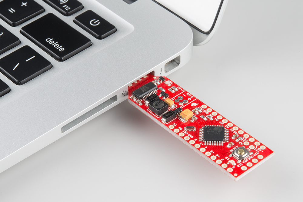
The SparkFun RedStick is a production version of the BadgerStick, which made an appearance at a trade show near you in the BadgerHack Badge. This version carries an NCP1402 boost regulator (as seen in the SparkFun 5.0v Step-Up Breakout Board, so it can run at 16MHz from a 6V down to a 2V input!
Covered in This Tutorial
- Hardware Overview -- A tour of the PCB.
- Powering the RedStick
- The Blink Sketch
- Using the 8x7 LED Array -- The 8x7 LED array library has been updated to work on this board!
- Adding a second voltage rail -- How to build an LDO onto the RedStick.
- Conclusion and Resources
Suggested Reading
- RedBoard Hookup Guide -- The RedBoard and RedStick have many similarities. Learn the ins-and-outs of getting either up and running in the Arduino IDE in this tutorial.
- BadgerHack -- The original BadgerStick (promo) documentation.
- Charlieplexed 8x7 LED Array Github -- If you would like more information on how the 8x7 LED array is programmed, check out the code files.
Hardware Overview
The following lists the features of the RedStick:
- A boost regulator providing 5V to the Atmega328p from an input range of 2 to 6 volts.
- 16 MHz system clock (allowed because of the additional supply voltage)
- Uno compatible in the Arduino IDE. Simply select the board "Arduino/Genuino Uno" and go!
- USB end matches standard USB thickness and width.
What the RedStick is not:
- A RedBoard -- it doesn't provide 3.3 volts, only 5.
- A battery charger -- The RedStick turns off the battery when plugged into a USB port.
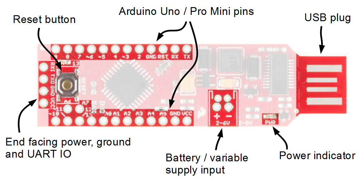
The following table lists all of the pins on the RedStick and their functionality.
| Pin Silk |
Function | Notes |
|---|---|---|
| TX | Serial transmit |
This is serial data coming out of the RedStick. |
| RX | Serial Receive |
This is serial data coming in |
| 2 | Digital |
|
| ~3 | Digital with PWM |
|
| 4 | Digital | |
| ~5 | Digital with PWM |
|
| ~6 | Digital with PWM |
|
| 7 | Digital | |
| 8 |
Digital | |
| 9 | Digital | |
| ~10 | Digital / PWM / SS |
|
| ~11 |
Digital / PWM / MOSI |
SPI bus |
| 12 | PWM / MISO |
SPI bus |
| 13 | Digital / SCK / LED |
SPI bus |
| A0 | Digital / Analog |
|
| A1 | Digital / Analog |
|
| A2 | Digital / Analog |
|
| A3 |
Digital / Analog |
|
| A4 |
Digital / Analog / SDA |
I2C bus -- some applications require pull-up |
| A5 |
Digital / Analog / SCL |
I2C bus-- some applications require pull-up |
| A6 | Analog |
Analog only! |
| A7 | Analog | Analog only! |
| RXI |
Serial Receive |
Electrically tied to RX |
| TXI | Serial Transmit |
Electrically tied to TX |
| VCC |
Microprocessor Power (Boost output) |
If using as input, supply regulated 5.0 v |
| GND | Ground | |
| + | Battery Positive |
Supply 2.0 to 6.0 volts |
| - | Battery Negative |
This is also GND |
Powering the RedStick
The RedStick was designed to allow two sources of power.
- Power directly from the USB port.
- Power with 2-6 volts on the battery terminals.
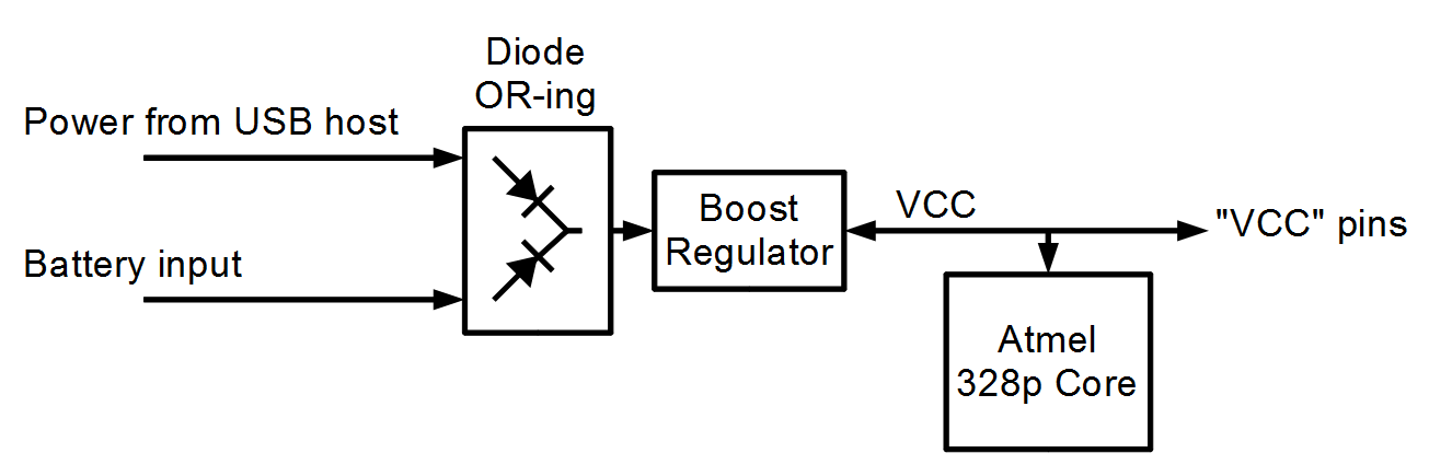
Functional Description
When power is applied to the USB port, it will not flow into the battery. Alternately, if the USB voltage is lower than the battery, power will not flow into the USB host.
To use AA cells, for example in a battery holder such as a 2xAA Holder with switch, solder the wires directly into the battery terminal holes, matching red to positive.
To use a rechargeable battery, such as a 1 Ah Lithium Ion battery, solder a JST connector into the smaller, 2mm spaced holes and attach the battery. Again match red with positive.
Notes on DC-DC converters
The RedStick uses a boost circuit to convert a low voltage ( > 2.0 volts DC ) to 5 volts DC. This DC-DC conversion is fairly common in today's world where a liner regulator is not efficient enough. This boost circuit measured around 83% efficient.
Here's a couple concepts to think about related to DC-DC converters
DC-DC converters and power
Ideally, DC-DC converters would be 100% efficient. In the math model, this means that power out = power in. So, if the converter is delivering 200mA at 5V, by the definition of electrical power, that's 1W (P = V * I). If we're consuming 1W from the output, we must be supplying 1W to the input. If the input is a battery at 3V, supplying 1W, it must be supplying 330mA. That's more than we're getting out!
As the input voltage to a DC-DC converter drops, the current consumption increases to maintain the output load.
This also applies to LED and CCFL bulbs that aren't dimmer compatible. As the dimmer decreases the voltage, the current increases and fries the dimmer circuit because it was designed for resistive loads (incandescents) that behave as Ohm's law indicates.
Drawbacks of DC-DC converters
The appeal of DC-DC converters is the low cost of the completed circuit. This is because inductors are used in place of transformers. The inductors operate at a high frequency so that the size can be made small, which makes them cheap. The control circuitry is a logic system that chooses when, and how fast, to operate the inductor in order to build up the necessary voltage on the output. This switching frequency can be seen as ripple on the output side of the DC-DC converter, depending on the loading of the circuit.
This DC-DC converter produces between 30 and 170 mV ripple in the 5kHz to 250kHz range, with optimal performance between 2.5-4.5 volts (typical battery voltages).
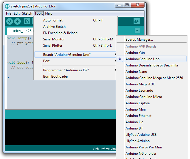
Example: The Blink Sketch
The RedStick comes with the blink sketch loaded and running, so the LED (pin 13) will toggle every second. This section shows how to get back to this basic sketch using the Arduino IDE.

To re-load the sketch, select the Arduino/Genuino Uno board from the menu, select the basic example blink, and press upload.
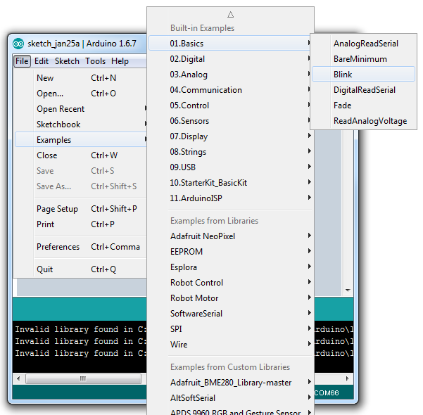
Now compile and run! That's all there is to it!
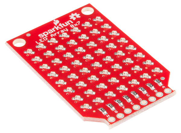
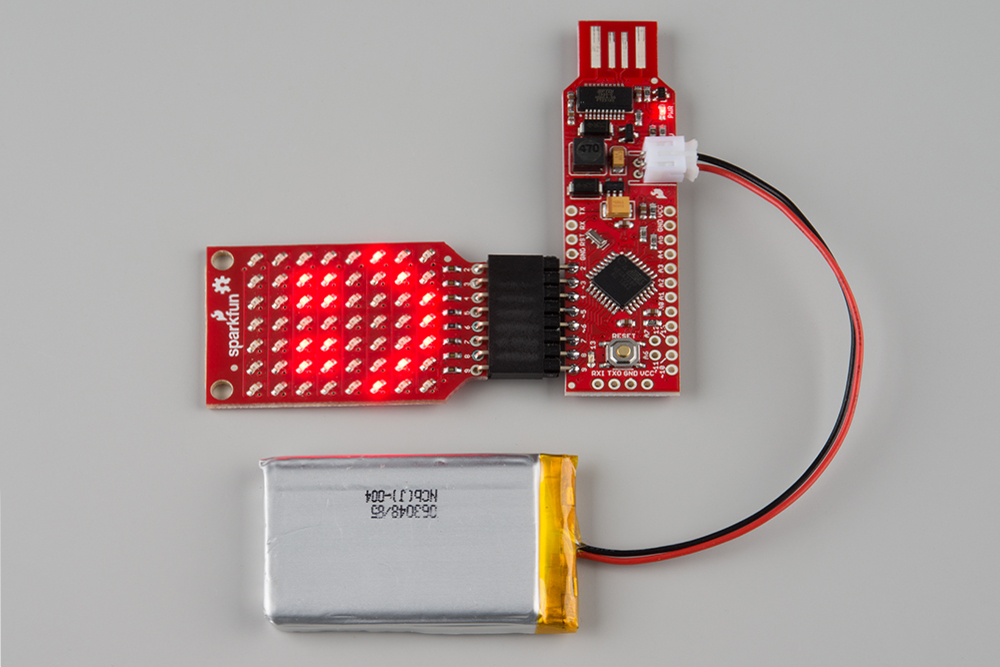
Example: Using the 8x7 LED Array
If you would like to use an 8x7 LED Array with the RedStick as with the BadgerStick, you can! The libraries have been updated to use F_CPU to set scroll speeds for 4, 8, and 16MHz boards.
Install the Arduino library
The 8x7 LED array has its own library. It is available as a github repository called SparkFun_LED_Array_8x7_Arduino_Library. It is not part of the library manager and will need to be manually installed (Drop it in your /libraries folder).
For more information, view this guide to installing Arduino libraries
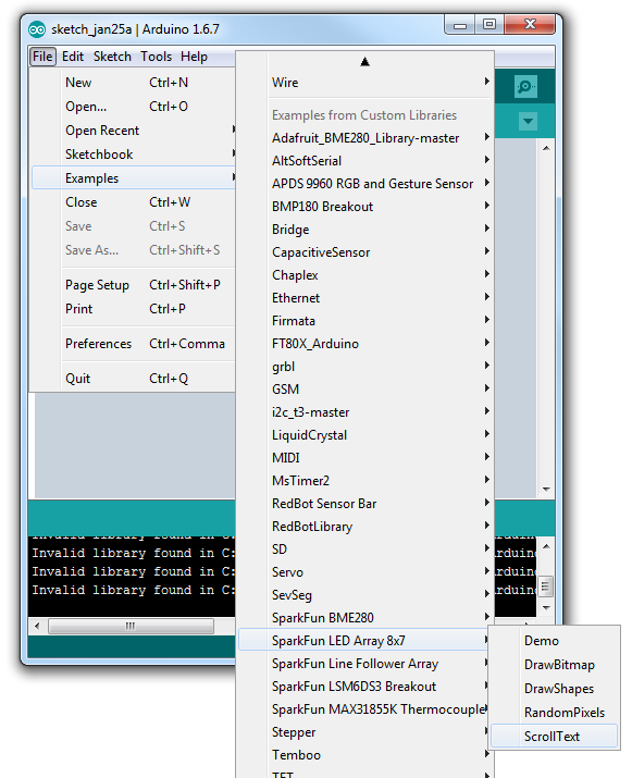
Run the example sketch
Under examples, select the 8x7 library, then the example sketch "ScrollText". This sketch displays scrolling text on the 8x7 LED array, but the library can also be used to draw individual pixels, shapes, and bitmaps.
Compile and run the sketch. The example text Hello. :) and Let's scroll! should scroll across the array. From this point the text can be changed, or the other features of the library can be used. Check out the BadgerHack 'Make a Game' section for example code that uses the 8x7 API.
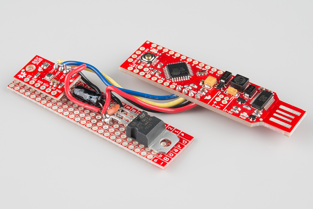
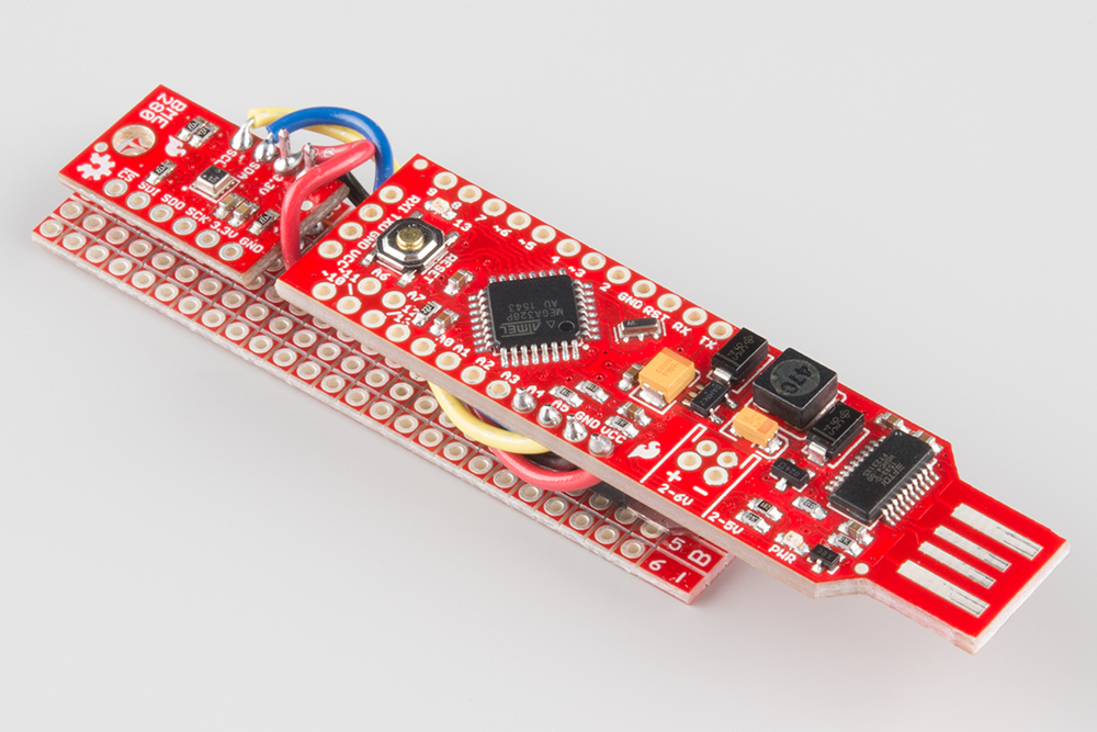
Example: Adding a Second Voltage Rail
Not all projects are LEDs and digital logic. If you want to add devices that operate at voltages other than 5.0 volts, a low-dropout regulator (LDO) can be added to solve the problem. Here, I've used basic components to attach a BME280 atmospheric sensor to my RedStick. Of course, you could use a breadboard power supply stick. I didn't want the barrel jack and extra space used up, so I used discrete components.
This inexpensive wishlist gets you the regulator, plenty of caps, and plenty of proto board to get going.
Build the LDO circuit
Build the following circuit. Remember to mind polarity on the electrolytic capacitor, that the pin ordering is kind of counter-intuitive, and that the TO-220's tab is connected to the pin 2 and not ground.
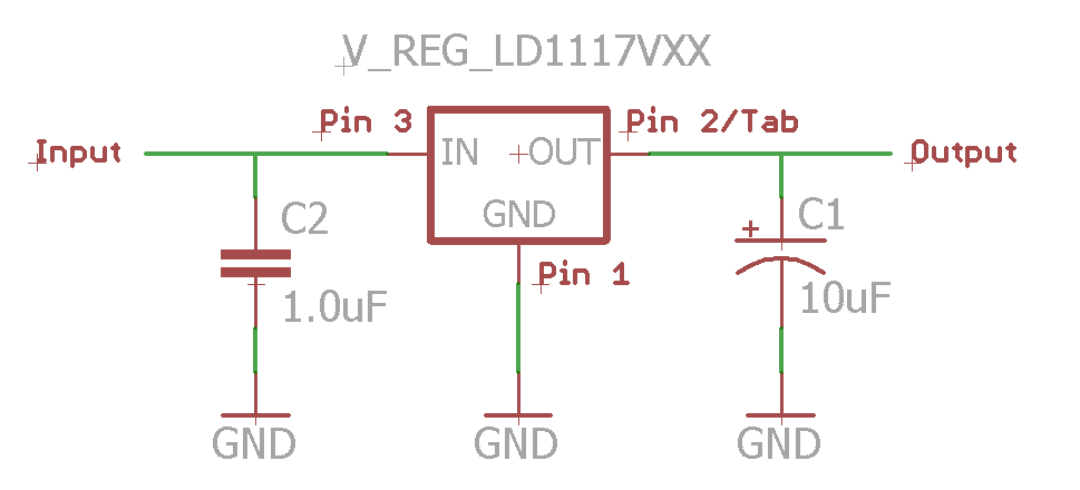
Connect the LDO circuit
To connect the LDO circuit to the RedStick,
- connect "GND" to a spare GND pin
- connect "Input" to VCC.
Now the "Output" is a regulated rail! In this case, 3.3 volts.
For this example, a BME280 is used. The BME280's ground is connected to the common GND pin while 3.3V is connected to the LDO's Output terminal. I2C serial lines are directly connected to the RedStick's A4 (SDA) and A5 (SCL) pins. The BME280's circuit board pulls these lines safely up to 3.3V.
Run the example
Run the BME280's example sketches. For information on use of the BME280, see the hookup guide.
Resources and Going Further
Here's a recap of the useful links from the guide and some extras that have information not covered. Remember, if you get stuck on a problem take a step back and list off what you do know, and have fun!
Resources used in this guide
- RedStick Schematic
- RedStick Eagle Files
- Datasheets (ATmega328p & NCP1402)
- BadgerStick GitHub repository
- BadgerArray GitHub repository
- BadgerHack Demos GitHub repository
Additional information and related topics
- RedBoard Hookup Guide -- Learn how to download and install the Arduino IDE.
- Unregulated Power Supply Tutorial -- notes on transformer ripple.
- Button Pad Hookup Guide -- creating button matrices.
- Diode Primer -- includes biasing LEDs.