Real Time Clock Module - RV-8803 (Qwiic) Hookup Guide
Introduction
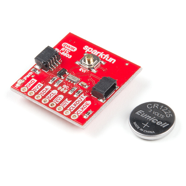
The Real Time Clock Module - RV-8803 (Qwiic) is a Qwiic-enabled breakout board for the RV-8803 RTC module. The RV-8803 boasts some impressive features including a temperature compensated crystal, extremely precise time-keeping, low power consumption, time stamp event input along with a user-programmable timing offset value. It even has a programmable Clock Output to control precise timing for peripheral devices. The RV-8803 also has an improved I2C interface compared to the RV-1805 RTC that removes the need to sequence commands/writes to the device. This is particularly helpful if you are not using our Arduino Library to control the RTC.
In this hookup guide we will go over the unique features of the RV-8803 along with some Arduino examples demonstrating how to use those features. By the end of this tutorial you will have your Real Time Clock Module - RV-8803 (Qwiic) configured and tick-tocking away (well, ticking, maybe not tocking) for your next time-keeping project!
Required Materials
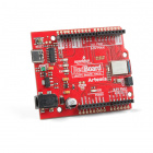
To follow along with this guide you will need a microcontroller to configure and communicate with the RTC Module breakout. Below are a few options that come Qwiic-enabled out of the box:
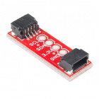
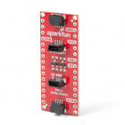
If your chosen microcontroller is not already Qwiic-enabled, you can add that functionality with one or more of the following items:
SparkFun Qwiic Shield for Arduino Nano
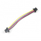
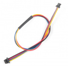
DEV-16130You will also want at least one Qwiic cable to connect your RTC to your microcontroller.
Qwiic Cable - 100mm
PRT-14427Qwiic Cable - 50mm
PRT-14426Qwiic Cable - 200mm
PRT-14428Qwiic Cable - 500mm
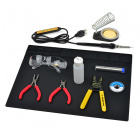
PRT-14429Some of the examples demonstrate how to use more than just the I2C pins. If you want to follow along with them you will need to solder to the EVI, INT, CLKOUT and CLKOE pins broken out on the board. Click the button below to see some recommended soldering tools and materials if you need them.
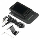
Finally, if you want to fine tune the RV-8803's oscillator for extremely precise time keeping you will need to use an oscilloscope or logic analyzer to calibrate it. Click the button below to see some options for oscilloscopes and logic analyzers if you need one.
Suggested Reading
If you aren't familiar with the Qwiic system, we recommend reading here for an overview:
 |
| Qwiic Connect System |
We also recommend taking a look at the hookup guides for the Qwiic Shields listed above if you plan on using one of them. Brushing up on your skills in I2C is also recommended as all Qwiic sensors communicate via I2C.
