Real Time Clock Module - RV-8803 (Qwiic) Hookup Guide
 El Duderino,
  Englandsaurus
Hardware Overview
The heart of this breakout is the RV-8803 Real Time Clock module from Micro Crystal. In this section we'll cover most of the features and characteristics of the RV-8803 and this breakout but if you are looking for a more thorough synopsis of the RV-8803, take a look through the Application Manual . The table below lists some of the operating characteristics of the RV-8803.
| Characteristic | Value |
|---|---|
| Operating Voltage Range | 1.5V - 5.5V |
| Time Accuracy (Temp. Compensated -40° to +85°C) | +/-3 ppm |
| Time Accuracy (Temp. Compensated +85° to +105°C) | +/-7 ppm |
| Current Consumption | 240 nA (Typ.) to 350 nA |
| I2C Address | 0x64 |
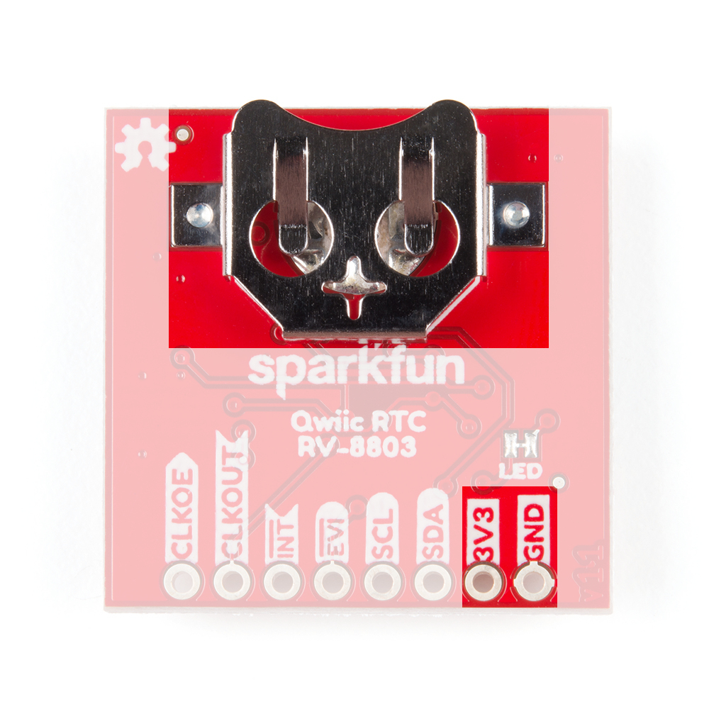
Power
There are two primary ways to power the SparkFun Real Time Clock Module - RV-8803 (Qwiic). The best and easiest way is through the Qwiic Connectors on either side of the board. When used with any of our Qwiic-enabled boards or our Qwiic Shields, this voltage will be 3.3V. The other power input is the 3.3V pin broken out. The board also includes a 3V 47mAh battery in the 12mm coin cell battery holder on the back for backup power.
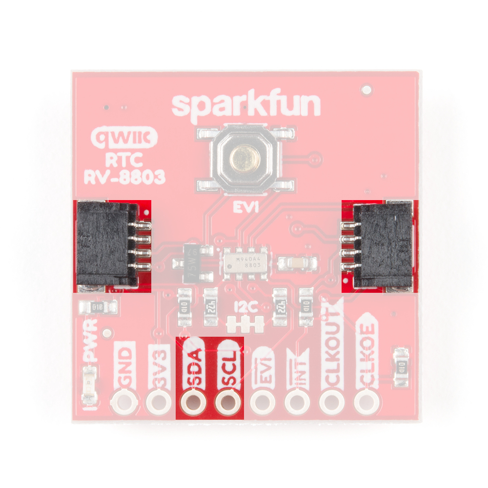
Qwiic and I2C Interface
The easiest way to use the Real Time Clock Module - RV-8803 (Qwiic) is with the Qwiic connect system. Just connect the board using a Qwiic Cable to your microcontroller to start talking to it. Alternatively, you can solder to the I2C pins broken out on the board. The 7-bit I2C unshifted address is 0x32 (0110010b). This is a hardware set address and there are no alternate peripheral addresses for the RV-8803. If you need multiple RTC's on a single I2C bus you will need to use a multiplexer or mux like the Qwiic Mux Breakout - 8 Channel.
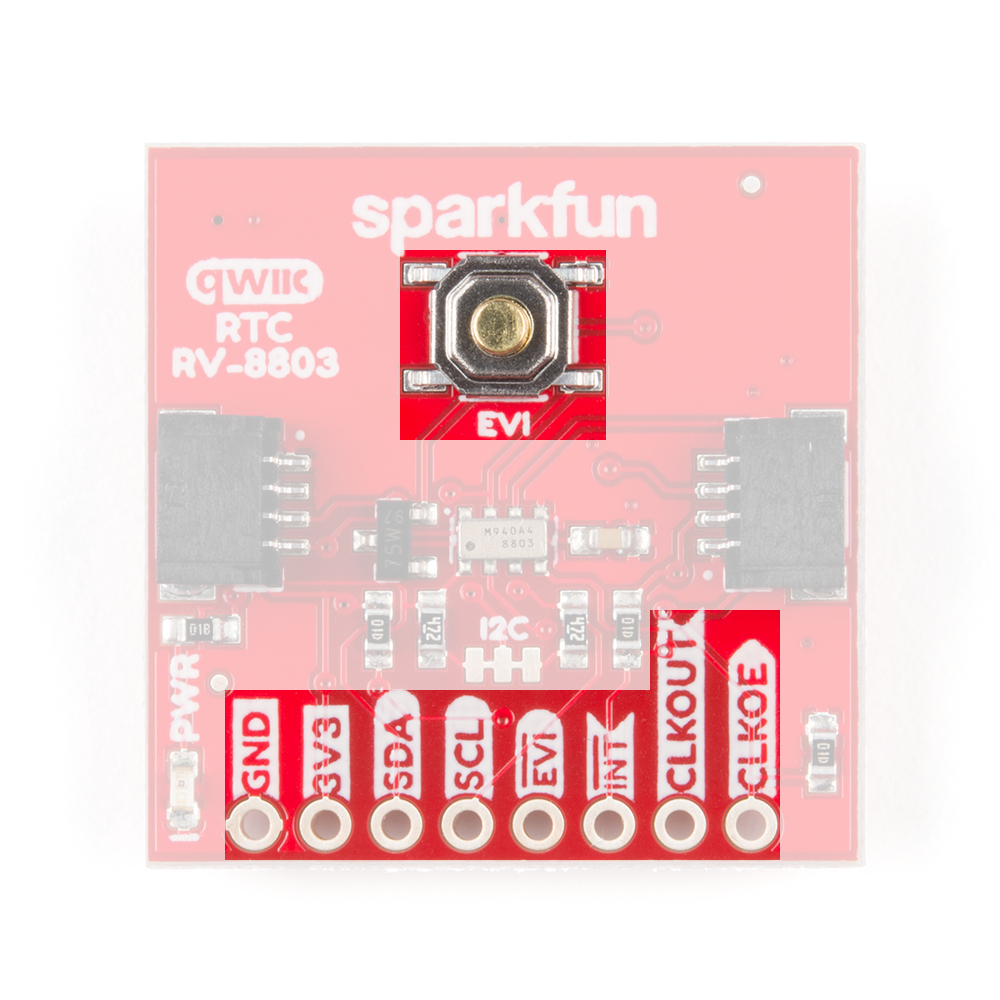
Pin Descriptions
While the Qwiic interface is the easiest and fastest way to start using your RTC, there are several other pins for extra functionality broken out. You will need to either solder to these pins to make use of them or you can create a temporary connection using something like these IC Hooks. The table below outlines all of the pins broken out on the RTC and summarizes their functionality.
| Pin Label | Pin Function | Input/Output | Functionality Notes |
|---|---|---|---|
| GND | Ground | Input | 0V/Common Voltage |
| 3.3V | Power Supply | Input | Power Supply voltage range is 1.5-3.3V |
| SDA | I2C Data Signal | Bi-directional | Bi-directional data line. Voltage should not exceed power supply (e.g. 3.3V). |
| SCL | I2C Clock Signal | Input | Clock signal. Voltage should not exceed power supply (e.g. 3.3V). |
| EVI | Event Input | Input/Output | External event interrupt pin with Time Stamp Function. Active LOW by default. Tied to the button labeled EVI for easy use. |
| INT | Interrupt Output | Output | Open-drain, active LOW. Used to output Alarm, Periodic Countdown Timer, Periodic Time Update and External Event Interrupt signals. Pulled to 3.3V with 100k resistor. |
| CLKOUT | Clock Output | Output | Programmable square wave output for peripheral devices. Available frequencies are 32.768 kHz (default), 1024 Hz or 1Hz. Set on power-up and controlled by the state of CLKOE pin. When disabled, pin is high impedance. |
| CLKOE | Clock Output Enable | Input | Enables and disables the CLKOUT pin. If HIGH, CLKOUT is enabled and is in output mode. If LOW, CLKOUT is disabled. Pin is pulled to GND by default with a 100k resistor. |
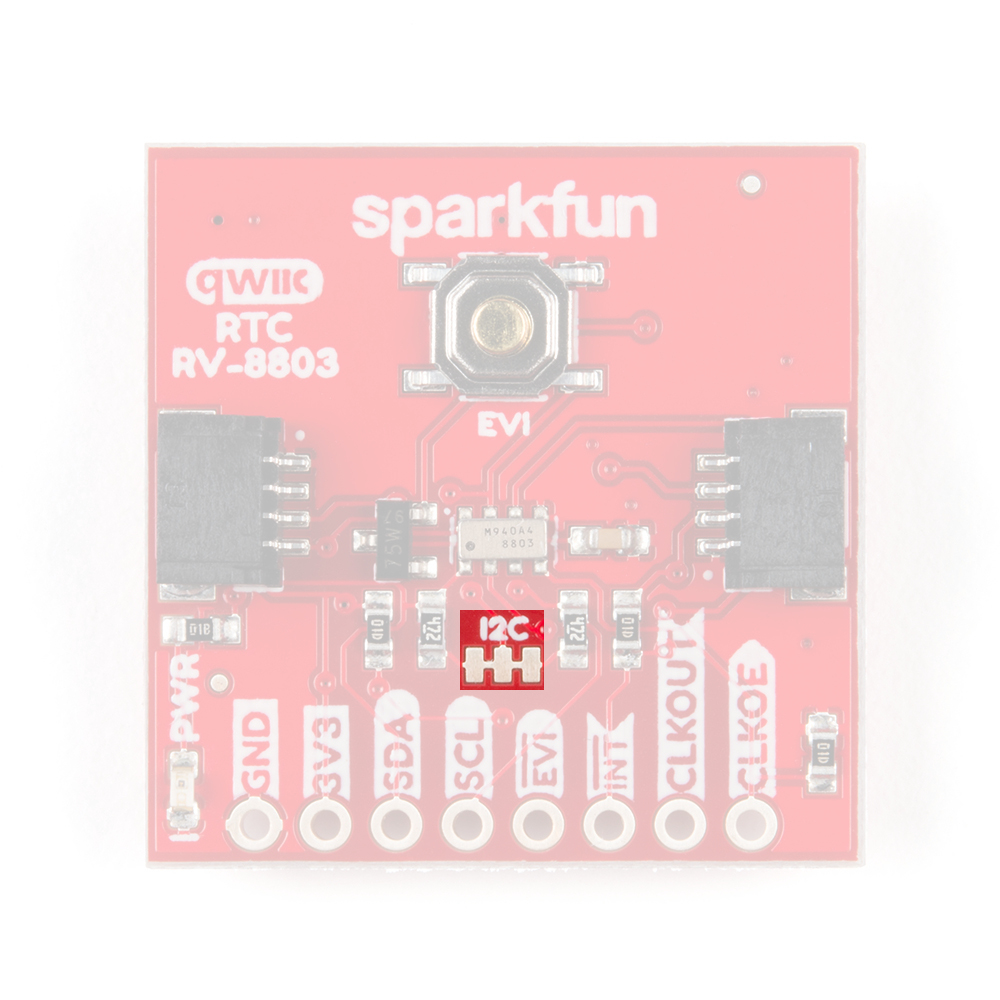
Jumpers
There are two jumpers on the SparkFun Real Time Clock Module - RV-8803 (Qwiic) labeled "I2C" and "LED". The I2C jumper is closed by default and can be opened by severing the trace between the three pads to disconnect the two 4.7k Ohm resistors from the SDA and SCL lines. Open this jumper for if you have many I2C devices on the same bus or to reduce current draw for low-power projects. The LED jumper is closed by default and enables the on board power LED. To open it, simply sever the trace in between the two jumper pads to disconnect the power LED (particularly useful for low-power applications). Note: The power LED is tied to the 3.3V input and is not powered by the backup battery.
 |
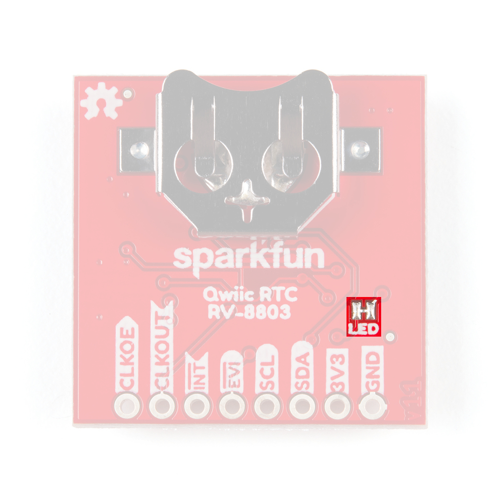 |
| I2C Jumper highlighted | LED Jumper Highlighted |
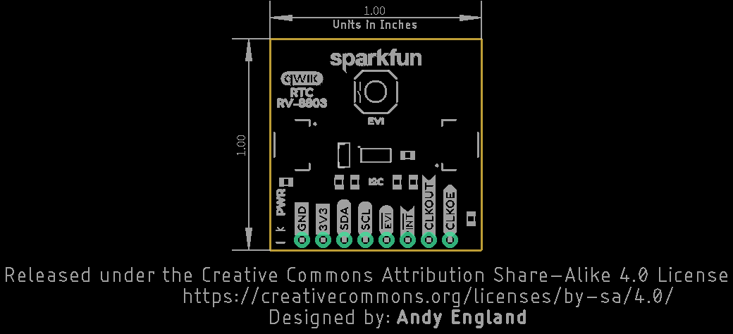
Board Dimensions
The SparkFun Real Time Clock Module - RV-8803 (Qwiic) is built to the standard 1 x 1" size for Qwiic Breakouts. One thing you may notice is this board's lack of mounting holes. In order to fit the 1 x 1" standard for Qwiic Breakouts, there was no space for mounting holes as the battery holder takes the space normally reserved for those mounting holes.