Raspberry Pi SPI and I2C Tutorial
 Byron J.,
  Shawn Hymel
SPI on Pi
Configuration
The SPI peripheral is not turned on by default. There are two methods to adjust the settings. To enable it, do the following.
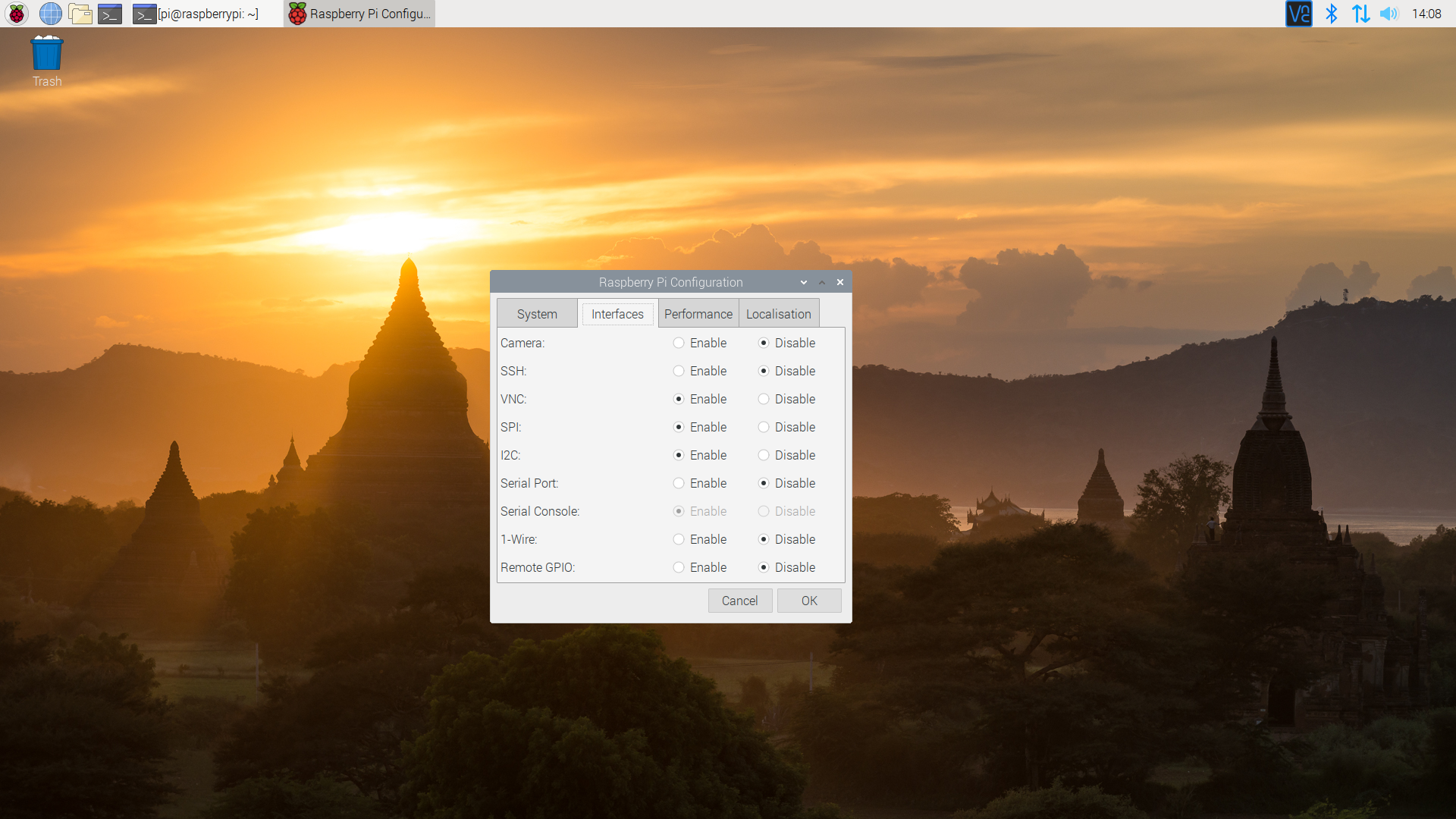
Raspberry Pi Configuration via Desktop GUI
You can use the Desktop GUI by heading to the Pi Start Menu > Preferences > Raspberry Pi Configuration.
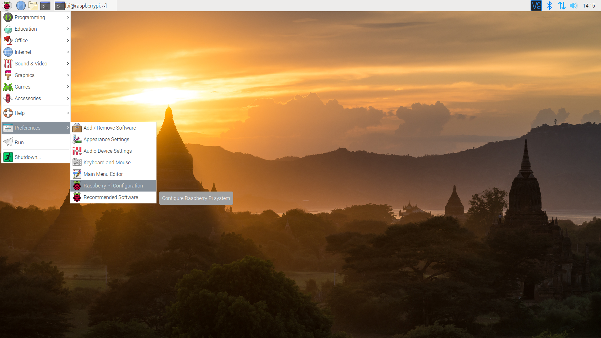
A window will pop up with different tabs to adjust settings. What we are interested is the Interfaces tab. Click on the tab and select Enable for SPI. At this point, you can enable additional interfaces depending on your project needs. Click on the OK button to save.
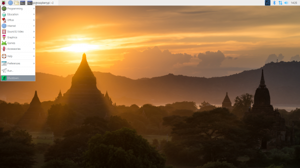
We recommend restarting your Pi to ensure that the changes to take effect. Click on the Pi Start Menu > Preferences > Shutdown. Since we just need to restart, click on the Restart button.
 |
 |
| Shutdown | Turn Off, Restart, Log Off |
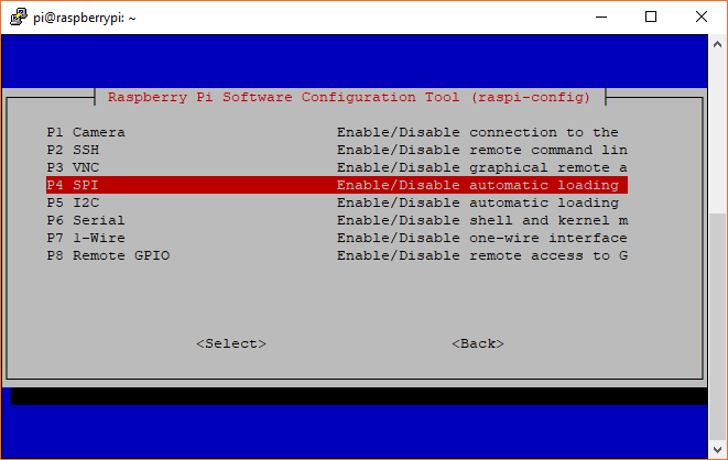
raspi-config Tool via Terminal
If you are using a terminal, you will need to:
- Run
sudo raspi-config. - Use the down arrow to select
5 Interfacing Options - Arrow down to
P4 SPI. - Select
yeswhen it asks you to enable SPI, - Also select
yesif it asks about automatically loading the kernel module. - Use the right arrow to select the
<Finish>button. - Select
yeswhen it asks to reboot.
The system will reboot. When it comes back up, log in and enter the following command
language:bash
ls /dev/*spi*
The Pi should respond with
language:bash
/dev/spidev0.0  /dev/spidev0.1
These represent SPI devices on chip enable pins 0 and 1, respectively. These pins are hardwired within the Pi. Ordinarily, this means the interface supports at most two peripherals, but there are cases where multiple devices can be daisy-chained, sharing a single chip enable signal.
Programming Example
Required Materials
- The 40-pin Pi Wedge.
- A Raspberry Pi B+ or Pi 2 Model B single board computer.
- A Solderless Breadboard.
- Some jumper wires.
- Headers of your choice.
- A Serial 7-Segment display.
The Serial 7-Segment display is particularly useful for testing serial interfaces, because it can accept command from a UART, SPI, or I2C. Make sure to solder header pins on the 7-segment display before wiring.
Hookup Table
The display was connected to the Pi, via the Pi Wedge, as follows.
| Raspberry Pi Signal | Serial 7-seg Signal |
| GND | GND |
| 3.3V | VCC |
| CE1 | SS (Shift Select) |
| SCK | SCK |
| MOSI | SDI |
| MISO | SDO |
The test hardware looked like this.

Sample C++ Program
language:c
/******************************************************************************
spitest.cpp
Raspberry Pi SPI interface demo
Byron Jacquot @ SparkFun Electronics>
4/2/2014
https://github.com/sparkfun/Pi_Wedge

A brief demonstration of the Raspberry Pi SPI interface, using the SparkFun
Pi Wedge breakout board.

Resources:

This example makes use of the Wiring Pi library, which streamlines the interface
to the the I/O pins on the Raspberry Pi, providing an API that is similar to the
Arduino.  You can learn about installing Wiring Pi here:
https://github.com/WiringPi/WiringPi/releases

The wiringPi SPI API is documented here:
https://projects.drogon.net/raspberry-pi/wiringpi/spi-library/

The init call returns a standard file descriptor.  More detailed configuration
of the interface can be performed using ioctl calls on that descriptor.
See the wiringPi SPI implementation (wiringPi/wiringPiSPI.c) for some examples.
Parameters configurable with ioctl are documented here:
http://git.kernel.org/cgit/linux/kernel/git/torvalds/linux.git/tree/Documentation/spi/spidev

Hardware connections:

This file interfaces with the SparkFun Serial 7 Segment display:
https://www.sparkfun.com/products/11629

The board was connected as follows:
(Raspberry Pi)(Serial 7 Segment)
GND  -> GND
3.3V -> Vcc
CE1  -> SS (Shift Select)
SCK  -> SCK
MOSI -> SDI
MISO -> SDO

To build this file, I use the command:
>  g++ spitest.cpp -lwiringPi

Then to run it, first the spi kernel module needs to be loaded.  This can be
done using the GPIO utility.
> gpio load spi
> ./a.out

This test uses the single-segment mode of the 7 segment display.  It shifts a
bit through the display characters, lighting a single character of each at a
time.

Development environment specifics:
Tested on Raspberry Pi V2 hardware, running Raspbian.
Building with GCC 4.6.3 (Debian 4.6.3-14+rpi1)

This code is beerware; if you see me (or any other SparkFun employee) at the
local, and you've found our code helpful, please buy us a round!

Distributed as-is; no warranty is given.
******************************************************************************/

#include <iostream>
#include <errno.h>
#include <wiringPiSPI.h>
#include <unistd.h>

using namespace std;

// channel is the wiringPi name for the chip select (or chip enable) pin.
// Set this to 0 or 1, depending on how it's connected.
static const int CHANNEL = 1;

int main()
{
   int fd, result;
   unsigned char buffer[100];

   cout << "Initializing" << endl ;

   // Configure the interface.
   // CHANNEL insicates chip select,
   // 500000 indicates bus speed.
   fd = wiringPiSPISetup(CHANNEL, 500000);

   cout << "Init result: " << fd << endl;

   // clear display
   buffer[0] = 0x76;
   wiringPiSPIDataRW(CHANNEL, buffer, 1);

   sleep(5);

   // Do a one-hot bit selection for each field of the display
   // It displays gibberish, but tells us that we're correctly addressing all
   // of the segments.
   for(int i = 1; i <= 0x7f; i <<= 1)
   {
      // the decimals, colon and apostrophe dots
      buffer[0] = 0x77;
      buffer[1] = i;
      result = wiringPiSPIDataRW(CHANNEL, buffer, 2);

      // The first character
      buffer[0] = 0x7b;
      buffer[1] = i;
      result = wiringPiSPIDataRW(CHANNEL, buffer, 2);

      // The second character
      buffer[0] = 0x7c;
      buffer[1] = i;
      result = wiringPiSPIDataRW(CHANNEL, buffer, 2);

      // The third character
      buffer[0] = 0x7d;
      buffer[1] = i;
      result = wiringPiSPIDataRW(CHANNEL, buffer, 2);

      // The last character
      buffer[0] = 0x7e;
      buffer[1] = i;
      result = wiringPiSPIDataRW(CHANNEL, buffer, 2);

      // Pause so we can see them
      sleep(5);
   }

   // clear display again
   buffer[0] = 0x76;
   wiringPiSPIDataRW(CHANNEL, buffer, 1);

}
When you built wiringPi, you might have noticed the statement about how to compile applications against it.
language:bash
NOTE: To compile programs with wiringPi, you need to add:
    -lwiringPi
to your compile line(s) To use the Gertboard, MaxDetect, etc.
code (the devLib), you need to also add:
    -lwiringPiDev
to your compile line(s).
Thus, we compile using the command.
language:bash
g++ spitest.cpp -l wiringPi -o spitest
Which generates an executable spitest. When we run ./spitest, it will exercise each of the segments of the display. It illuminates a segment in each digit for 5 seconds, before moving to the next segment. It takes about 40 seconds overall.
Sample Python Program
language:python
# spitest.py
# A brief demonstration of the Raspberry Pi SPI interface, using the Sparkfun
# Pi Wedge breakout board and a SparkFun Serial 7 Segment display:
# https://www.sparkfun.com/products/11629

import time
import spidev

# We only have SPI bus 0 available to us on the Pi
bus = 0

#Device is the chip select pin. Set to 0 or 1, depending on the connections
device = 1

# Enable SPI
spi = spidev.SpiDev()

# Open a connection to a specific bus and device (chip select pin)
spi.open(bus, device)

# Set SPI speed and mode
spi.max_speed_hz = 500000
spi.mode = 0

# Clear display
msg = [0x76]
spi.xfer2(msg)

time.sleep(5)

# Turn on one segment of each character to show that we can
# address all of the segments
i = 1
while i < 0x7f:

    # The decimals, colon and apostrophe dots
    msg = [0x77]
    msg.append(i)
    result = spi.xfer2(msg)

    # The first character
    msg = [0x7b]
    msg.append(i)
    result = spi.xfer2(msg)

    # The second character
    msg = [0x7c]
    msg.append(i)
    result = spi.xfer2(msg)

    # The third character
    msg = [0x7d]
    msg.append(i)
    result = spi.xfer2(msg)

    # The last character
    msg = [0x7e]
    msg.append(i)
    result = spi.xfer2(msg)

    # Increment to next segment in each character
    i <<= 1

    # Pause so we can see them
    time.sleep(5)


# Clear display again
msg = [0x76]
spi.xfer2(msg)
Save the program with a name like spitest.py, and run it with:
language:bash
python spitest.py
This will illuminate each segment in each character for 5 seconds before moving on to the next segment. It should take about 40 seconds for the whole program to run.