Raspberry Pi SPI and I2C Tutorial
 Byron J.,
  Shawn Hymel
I2C on Pi
Configuration
The I2C peripheral is not turned on by default. There are two methods to adjust the settings just like the SPI. To enable it, do the following.
Raspberry Pi Configuration via Desktop GUI
You can use the Desktop GUI by heading to the Pi Start Menu > Preferences > Raspberry Pi Configuration.
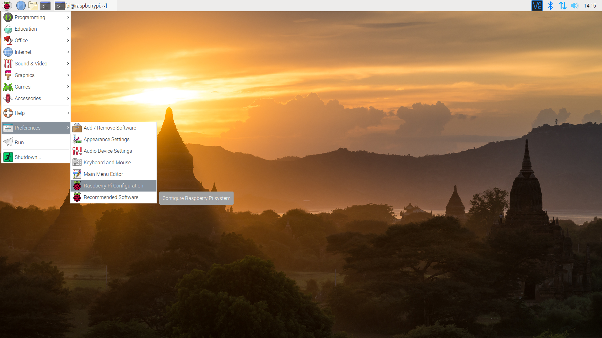
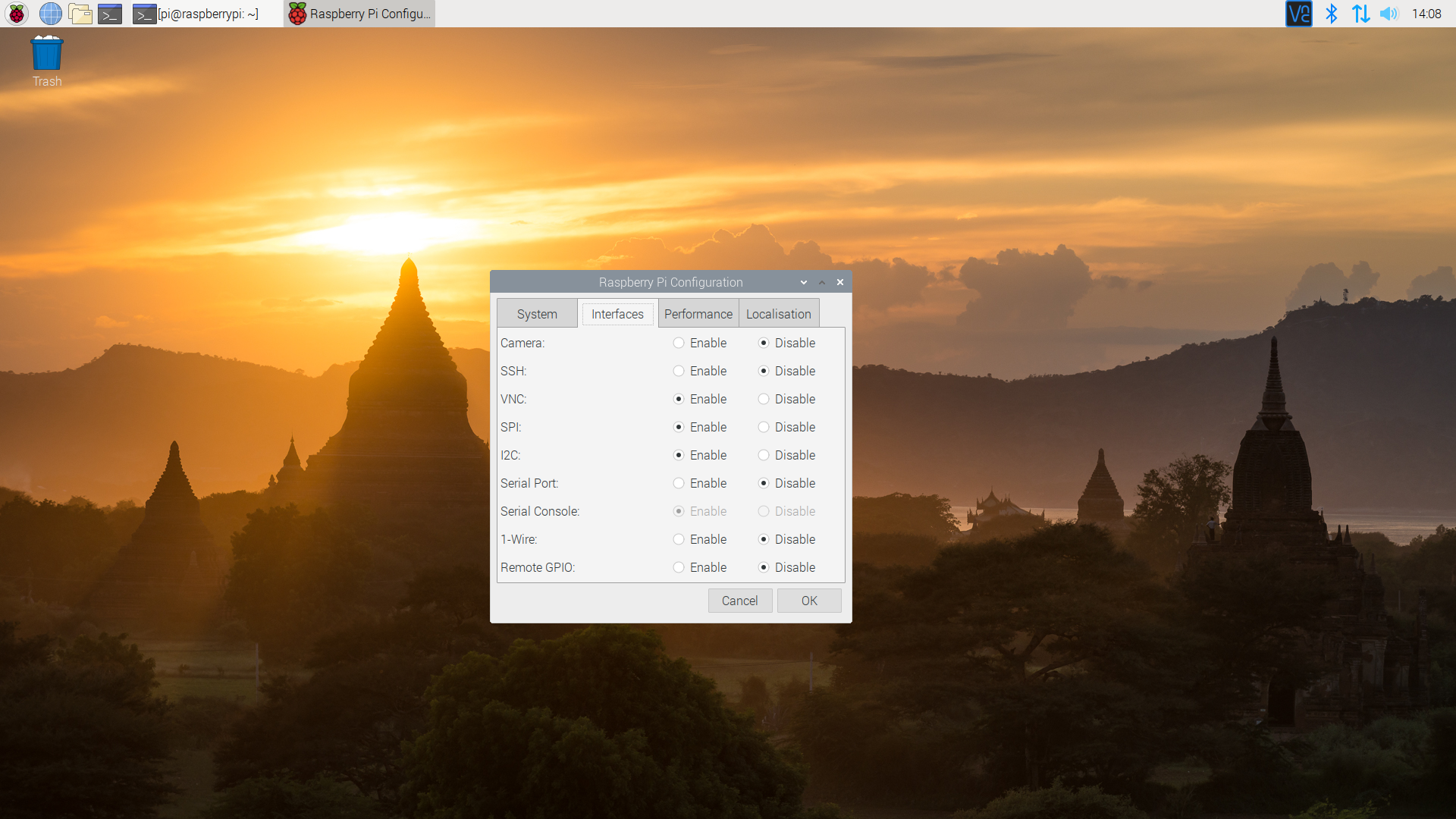
A window will pop up with different tabs to adjust settings. What we are interested is the Interfaces tab. Click on the tab and select Enable for I2C. At this point, you can enable additional interfaces depending on your project needs. Click on the OK button to same.
We recommend restarting your Pi to ensure that the changes to take effect. Click on the Pi Start Menu > Preferences > Shutdown. Since we just need to restart, click on the Restart button.
 |
 |
| Shutdown | Turn Off, Restart, Log Off |
raspi-config Tool via Terminal
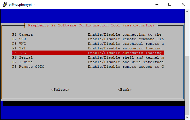
Like the SPI peripheral, I2C is not turned on by default. Again, we can use raspi-config to enable it.
- Run
sudo raspi-config. - Use the down arrow to select
5 Interfacing Options - Arrow down to
P5 I2C. - Select
yeswhen it asks you to enable I2C - Also select
yesif it asks about automatically loading the kernel module. - Use the right arrow to select the
<Finish>button. - Select
yeswhen it asks to reboot.
The system will reboot. when it comes back up, log in and enter the following command
language:bash
ls /dev/*i2c*
The Pi should respond with
language:bash
/dev/i2c-1
Which represents the user-mode I2C interface.
Utilities
There is a set of command-line utility programs that can help get an I2C interface working. You can get them with the apt package manager.
language:bash
sudo apt-get install -y i2c-tools
In particular, the i2cdetect program will probe all the addresses on a bus, and report whether any devices are present. Enter the following command in the command line. The -y flag will disable interactive mode so that you do not have to wait for confirmation. The 1 indicates that we are scanning for I2C devices on I2C bus 1 (e.g. i2c-1).
language:bash
i2cdetect -y 1
You will get an output from your Raspberry Pi similar to the output below.
language:bash
pi@raspberrypi:~/$ i2cdetect -y 1
     0  1  2  3  4  5  6  7  8  9  a  b  c  d  e  f
00:          -- -- -- -- -- -- -- -- -- -- -- -- --
10: -- -- -- -- -- -- -- -- -- -- -- -- -- -- -- --
20: -- -- -- -- -- -- -- -- -- -- -- -- -- -- -- --
30: -- -- -- -- -- -- -- -- -- -- -- -- -- -- -- --
40: -- -- -- -- -- -- -- -- -- -- -- -- -- -- -- --
50: -- -- -- -- -- -- -- -- -- -- -- -- -- -- -- --
60: 60 -- -- -- -- -- -- -- -- -- -- -- -- -- -- --
70: -- -- -- -- -- -- -- --
This map indicates that there is a peripheral at address 0x60. We can try to read and write its registers using the i2cget, i2cset and i2cdump commands.
Programming Example
Required Materials
- The 40-pin Pi Wedge.
- A Raspberry Pi B+ or Pi 2 Model B single board computer.
- A Solderless Breadboard.
- Some jumper wires.
- Header pins of your choice.
- An MCP4725 digital-to-analog converter.
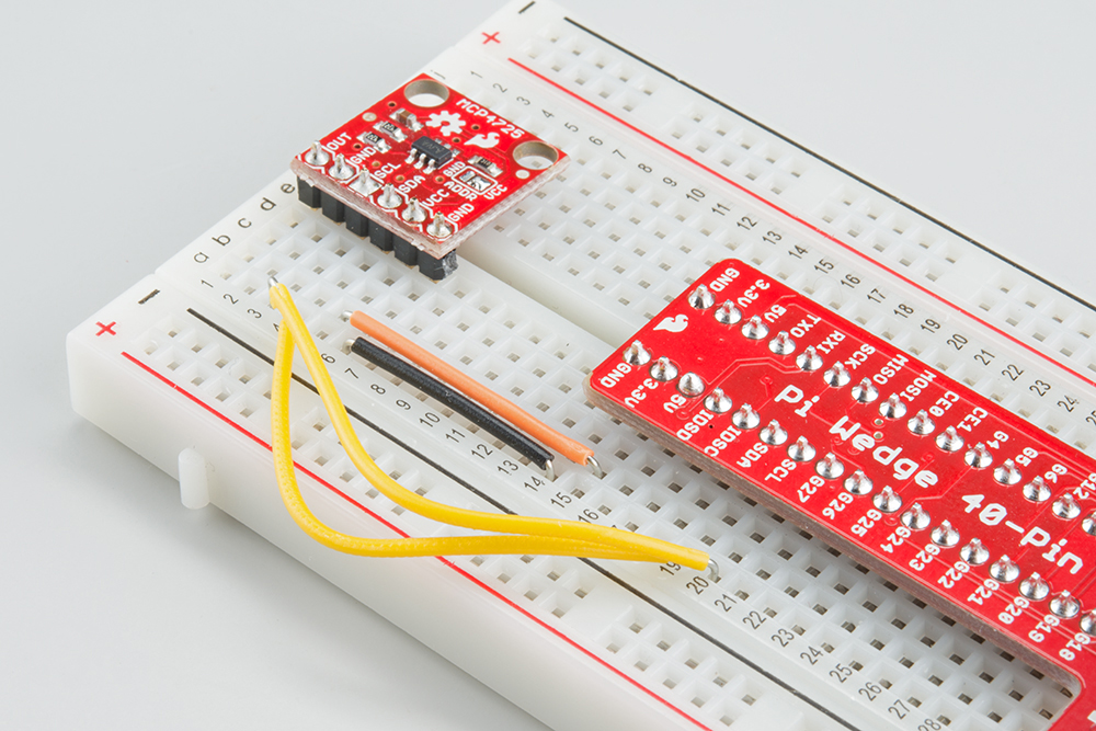
Hookup Table
The display was connected to the Pi, via the Pi Wedge, as follows.
| Raspberry Pi Signal | MCP4725 |
| GND | GND |
| 3.3V | VCC |
| SCL | SCL |
| SDA | SDA |
The test hardware looked like this.
Sample C++ Program
The following code writes successive values to the DAC, producing an sawtooth wave at its output pin.
language:c
/******************************************************************************
i2ctest.cpp
Raspberry Pi I2C interface demo
Byron Jacquot @ SparkFun Electronics>
4/2/2014
https://github.com/sparkfun/Pi_Wedge

A brief demonstration of the Raspberry Pi I2C interface, using the SparkFun
Pi Wedge breakout board.

Resources:

This example makes use of the Wiring Pi library, which streamlines the interface
the the I/O pins on the Raspberry Pi, providing an API that is similar to the
Arduino.  You can learn about installing Wiring Pi here:
https://github.com/WiringPi/WiringPi/releases

The I2C API is documented here:
https://projects.drogon.net/raspberry-pi/wiringpi/i2c-library/

The init call returns a standard file descriptor.  More detailed configuration
of the interface can be performed using ioctl calls on that descriptor.
See the wiringPi I2C implementation (wiringPi/wiringPiI2C.c) for some examples.
Parameters configurable with ioctl are documented here:
http://git.kernel.org/cgit/linux/kernel/git/torvalds/linux.git/tree/Documentation/i2c/dev-interface

Hardware connections:

This file interfaces with the SparkFun MCP4725 breakout board:
https://www.sparkfun.com/products/8736

The board was connected as follows:
(Raspberry Pi)(MCP4725)
GND  -> GND
3.3V -> Vcc
SCL  -> SCL
SDA  -> SDA

An oscilloscope probe was connected to the analog output pin of the MCP4725.

To build this file, I use the command:
>  g++ i2ctest.cpp -lwiringPi

Then to run it, first the I2C kernel module needs to be loaded.  This can be
done using the GPIO utility.
> gpio load i2c 400
> ./a.out

This will run the MCP through its output range several times.  A rising
sawtooth will be seen on the analog output.

Development environment specifics:
Tested on Raspberry Pi V2 hardware, running Raspbian.
Building with GCC 4.6.3 (Debian 4.6.3-14+rpi1)

This code is beerware; if you see me (or any other SparkFun employee) at the
local, and you've found our code helpful, please buy us a round!

Distributed as-is; no warranty is given.
******************************************************************************/

#include <iostream>
#include <errno.h>
#include <wiringPiI2C.h>

using namespace std;

int main()
{
   int fd, result;

   // Initialize the interface by giving it an external device ID.
   // The MCP4725 defaults to address 0x60.
   //
   // It returns a standard file descriptor.
   //
   fd = wiringPiI2CSetup(0x60);

   cout << "Init result: "<< fd << endl;

   for(int i = 0; i < 0x0000ffff; i++)
   {
      // I tried using the "fast write" command, but couldn't get it to work.
      // It's not entirely obvious what's happening behind the scenes as
      // regards to endianness or length of data sent.  I think it's only
      // sending one byte, when we really need two.
      //
      // So instead I'm doing a 16 bit register access.  It appears to
      // properly handle the endianness, and the length is specified by the
      // call.  The only question was the register address, which is the
      // concatenation of the command (010x = write DAC output)
      // and power down (x00x = power up) bits.
      result = wiringPiI2CWriteReg16(fd, 0x40, (i & 0xfff) );

      if(result == -1)
      {
         cout << "Error.  Errno is: " << errno << endl;
      }
   }
}
Build it and link it to wiringPi using the following command.
language:bash
g++ i2ctest.cpp -l wiringPi -o i2ctest
When you run i2ctest, the DAC will produce an analog sawtooth wave for a few seconds.
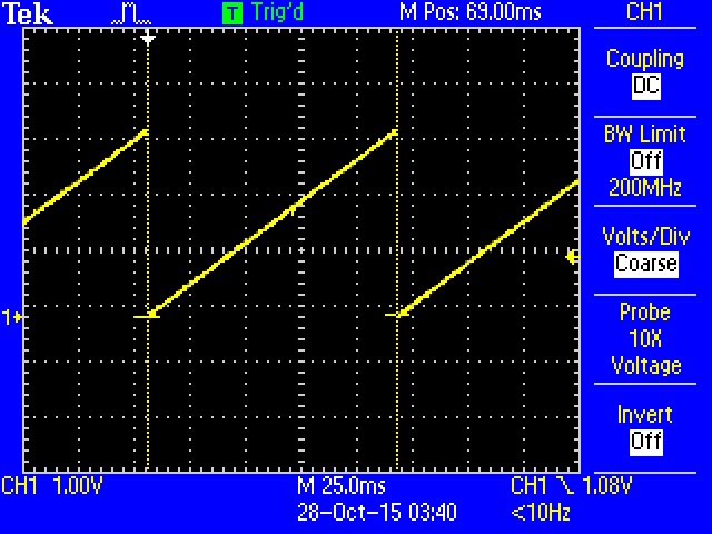
OUT pin Sample Python Program
language:python
# i2ctest.py
# A brief demonstration of the Raspberry Pi I2C interface, using the Sparkfun
# Pi Wedge breakout board and a SparkFun MCP4725 breakout board:
# https://www.sparkfun.com/products/8736

import smbus

# I2C channel 1 is connected to the GPIO pins
channel = 1

#  MCP4725 defaults to address 0x60
address = 0x60

# Register addresses (with "normal mode" power-down bits)
reg_write_dac = 0x40

# Initialize I2C (SMBus)
bus = smbus.SMBus(channel)

# Create a sawtooth wave 16 times
for i in range(0x10000):

    # Create our 12-bit number representing relative voltage
    voltage = i & 0xfff

    # Shift everything left by 4 bits and separate bytes
    msg = (voltage & 0xff0) >> 4
    msg = [msg, (msg & 0xf) << 4]

    # Write out I2C command: address, reg_write_dac, msg[0], msg[1]
    bus.write_i2c_block_data(address, reg_write_dac, msg)
Save the program with a name like i2ctest.py, and run it with the command:
language:bash
python i2ctest.py
You should see a sawtooth wave appear on the DAC output. If you connect an oscilloscope, you should get an image like the one shown in the C++ example. Note that Python is much slower than C/C++! The period of the sawtooth wave in the C++ example was around 100 ms whereas the period of the wave in the Python example was close to 1.8 seconds.
Be aware that SMBus is a protocol layer separate from but built on top of I2C. Some features of I2C may not be available with SMBus. For example, SMBus cannot handle clock stretching, so sensors that require it to communicate will not work with the smbus package.
To learn more about the smbus protocol, see the official kernel documentation.