Qwiic TMP117 High Precision Digital Temperature Sensor Hookup Guide
 bboyho
Arduino Example Code
Example 1: Basic Readings
This example prints out the temperature in degrees Celsius and Fahrenheit. The beginning of the code is pretty much the same for the examples. The code initializes the I2C bus to communicate with the TMP117 and serial UART to pass the data to our Arduino serial monitor. We'll want to set the bus to fast mode as recommended by the datasheet. Once initialized, we'll check to see if the address matches the TMP117. By default, this is 0x48. If it matches, we'll continue running the sketch.
This particular example will check to see if the TMP117 measured and averaged the temperature readings. If there is data ready, the TMP117 will notify us from the configuration register. When ready, we'll read the temperature registers and output it out to the Arduino serial monitor.
If you have not already, open the example up from your Arduino menu and clicking on the example: File > Examples > SparkFun_High_Precision_Temperature_Sensor_TMP117_Qwiic > Example1_BasicReadings. Select your board (in this case Arduino/Genuino Uno and COM port that the board enumerated to. Hit the upload button. Open the serial monitor at 115200 baud to start reading the temperature readings. You should see something like the output below.
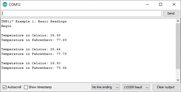
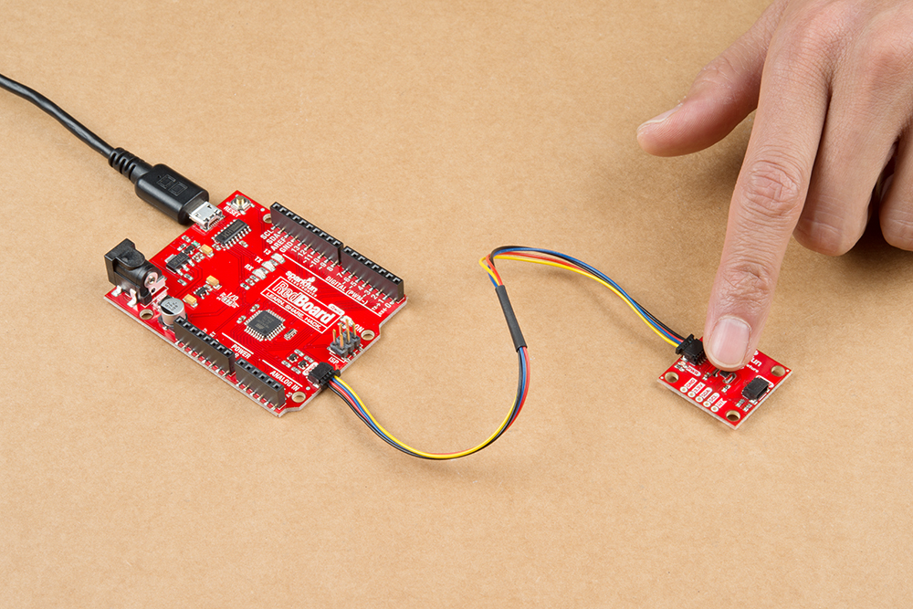
Try heating the sensor with your finger or lightly breathe some air across the sensor to watch the temperature values change! The third reading from the output shows the temperature rising after placing my finger on the temperature sensor. Remember, the sensor is taking a few readings and averaging them together before we are able see the output. Make sure to be patient with the output. If you need to output data faster, you can configure the conversion averaging times in example 6
Example 2: Alert Status
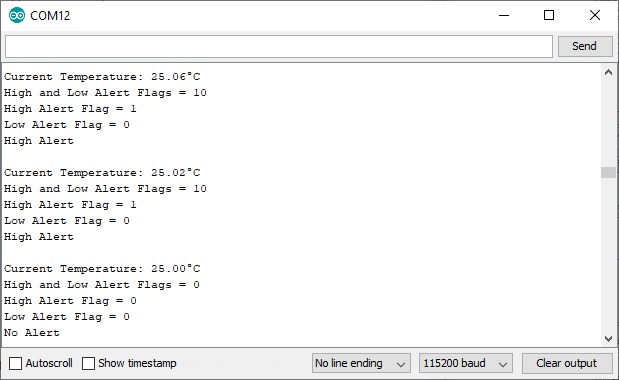
This example configures the serial I2C and UART like the first example. We'll set alert function mode and temperature limits in volatile memory. When ready, we'll check to see if the temperature exceeds the high or low limits. By default, the alert function mode is set to alert mode. We set it again just in case. If we above the high limit, the high alert flag will be raised and we will output high alert.. If we are below the low limit, the high alert flag will be raised and we will output the low alert. Otherwise, we will have message indicating that there is no alert.
If you have not already, open the example up from the Arduino menu and clicking on the example: File > Examples > SparkFun_High_Precision_Temperature_Sensor_TMP117_Qwiic > Example2_AlertStatuses. Select your board (in this case Arduino/Genuino Uno and COM port that the board enumerated to. Hit the upload button. Open the serial monitor at 115200 baud. You should see something like the output below.
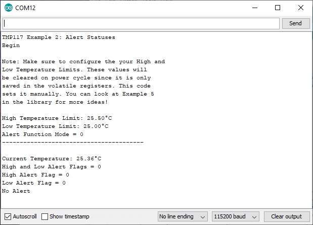
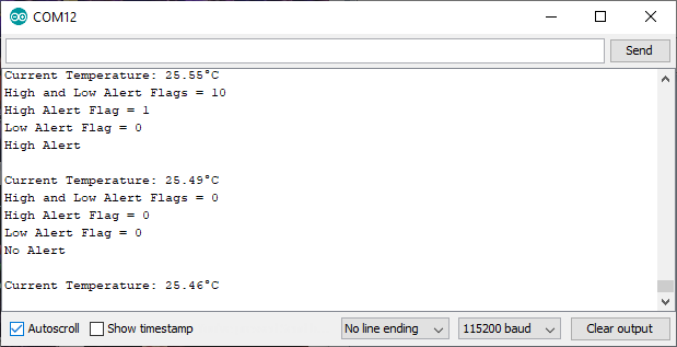
The current temperature reading at the time was 25.36°C. This is within the boundary of our temperature limits that we set so our alert flag is 0. You can adjust the limits as necessary but we made the temperature window narrow to easily test the functionality using the heat from our body. When we are outside the boundary limits, the alert flags will be set to 1 with their respective limits. As the temperature changes and is within our boundaries, the flag will be set back to 0.
 |
 |
| High Alert Flag Raised to 1 | Low Alert Flag Raised to 1 |
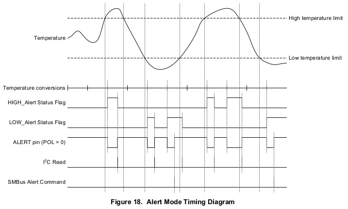
If you look at Figure 18 of the Alert Mode Timing Diagram on page 15 of the datasheet, the serial output and the voltage of the pin matches what we expect from the TMP117!
The example above shows what happens when we are in "alert mode." You'll notice that the flags and pin resets itself every time there is a read of the configuration register. If you modify the line that sets the alert function mode to "therm mode", the the flags behave slightly differently.
language:c
//.
//. somewhere in Example 2's setup(){} function
//.

  /*Note: Set to alert or therm mode. To change, simply adjust
  add or remove a `//` to the line.*/
  //sensor.setAlertFunctionMode(0);//set to alert mode
  sensor.setAlertFunctionMode(1);//set to therm mode
If the current temperature exceeds the high temperature limit, you'll notice that the alert flag will stay at 1 until the temperature is below our low temperature limit.

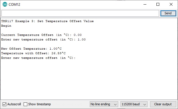
Example 3: Set Offset Temperature
In this example, you can adjust the offset temperature of the TMP117. This is useful if you need to adjust the temperature readings based on your system in case the location you are measuring is warmer or colder than the surrounding environment.
If you have not already, open the example up from the Arduino menu and clicking on the example: File > Examples > SparkFun_High_Precision_Temperature_Sensor_TMP117_Qwiic > Example3_SetOffsetTemperatureValue. Select your board (in this case Arduino/Genuino Uno and COM port that the board enumerated to. Hit the upload button. Open the serial monitor at 115200 baud. You will be asked to enter a temperature offset. After entering a value and hitting your ENTER key, the TMP117 will save the offset in its volatile memory.
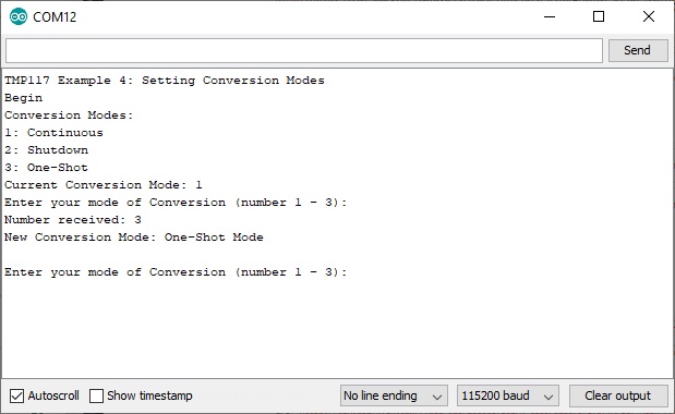
Example 4: Set Conversion Mode
You can change the continuous conversion mode. The default is in "continuous conversion mode". You can set it one-shot or shutdown mode for low power applications. In one-shot mode, the TMP117 will take one temperature reading. After one temperature reading, the sensor will enter low power shutdown mode. When the TMP117 is set to shutdown mode, all temperature conversions are aborted and the TMP117 will enter low power shutdown mode.
If you have not already, open the example up from the Arduino menu and clicking on the example: File > Examples > SparkFun_High_Precision_Temperature_Sensor_TMP117_Qwiic > Example4_SetConversionMode. Select your board (in this case Arduino/Genuino Uno and COM port that the board enumerated to. Hit the upload button. Open the serial monitor at 115200 baud. You will be asked to enter a temperature offset. After entering a value and hitting your ENTER key, the TMP117 will save the offset in its volatile memory.
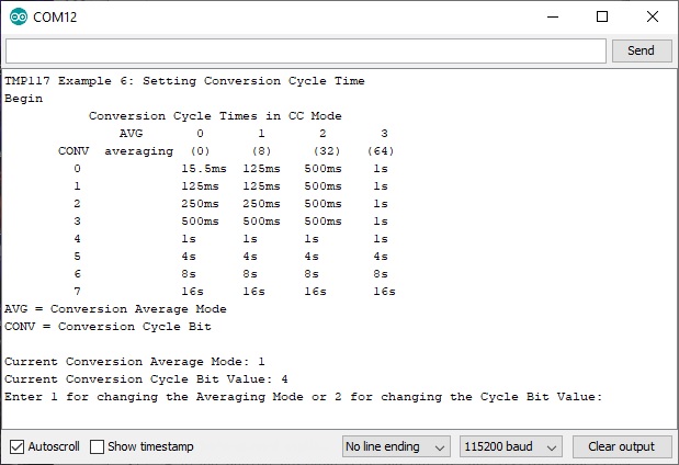
Example 6: Set Conversion Cycle Time
In this example, you can adjust the conversion cycle bit and the conversion averaging mode. You can reduce the amount of noise by adjusting these values. By decreasing the cycle average mode and conversion cycle bit, you will get faster readings but the data will start to become more noisy. By increasing the conversion average mode and conversion cycle bit, you will get more stable temperature readings. You will get a slower output because it is averaging the several data points together. However, the readings will be smoother. As stated in the datasheet on page 33 under 8.2.2.1 Noise and Averaging, you'll want higher averaging numbers whenever your "system environment is noisy (such as when measuring air flow temperatures, power supply fluctuations, intensive communication on a serial bus...)." Here's a table of the conversion cycle times from page 27 of the datasheet.
| AVG = 0 (0 Conversions) |
AVG = 1 (8 Conversions) |
AVG = 2 (32 Conversions) |
AVG = 3 (64 Conversions) |
|
|---|---|---|---|---|
| CONV = 0 | 15.5 ms | 125 ms | 500 ms | 1 sec |
| CONV = 1 | 125 ms | 125 ms | 500 ms | 1 sec |
| CONV = 2 | 250 ms | 250 ms | 500 ms | 1 sec |
| CONV = 3 | 500 ms | 500 ms | 500 ms | 1 sec |
| CONV = 4 | 1 sec | 1 sec | 1 sec | 1 sec |
| CONV = 5 | 4 sec | 4 sec | 4 sec | 4 sec |
| CONV = 6 | 8 sec | 8 sec | 8 sec | 8 sec |
| CONV = 7 | 16 sec | 16 sec | 16 sec | 16 sec |
If you have not already, open the example up from the Arduino menu and clicking on the example: File > Examples > SparkFun_High_Precision_Temperature_Sensor_TMP117_Qwiic > Example6_SetConversionCycleTime. Select your board (in this case Arduino/Genuino Uno and COM port that the board enumerated to. Hit the upload button. Open the serial monitor at 115200 baud.
More Examples
We only went over 5 of the examples. There's a few more in the library. Make sure to read through the description and comments in the code before trying out the additional examples that were not explained earlier!