Qwiic TMP117 High Precision Digital Temperature Sensor Hookup Guide
 bboyho
Hardware Overview
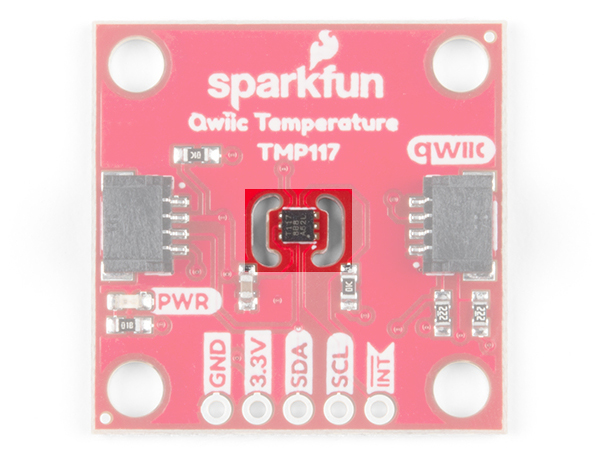
TMP117
The TMP117 is located on a tiny, isolated island between two slots that are cut into the PCB. This minimizes heat generated from components on the PCB and any errors that may result when taking temperature readings.
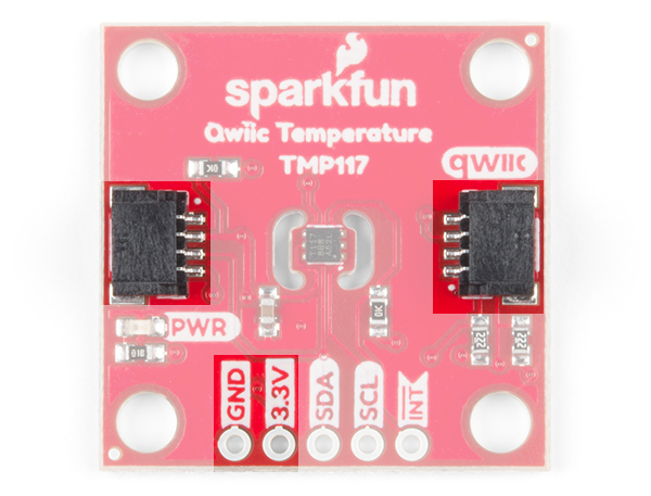
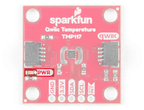
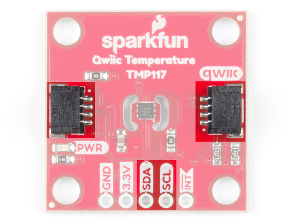
Power
The sensor has a low power consumption and is operates between 1.8V to 5.5V. To power the sensor on the breakout board, it utilizes 3.3V from the Qwiic connector. Depending on your application, you can also connect a power via the plated through holes for 3.3V and GND. The corresponding PWR LED will light up to indicate if the sensor is being powered.
 |
 |
I2C Pins
To communicate with the sensor, you will need an I2C bus. The Qwiic system makes it easy to connect the TMP117 to your projects via the Qwiic connector. You can add a Qwiic cable between the sensor and development board to start experimenting with the sensor in your projects. Depending on your application, you can also connect to the I2C pins via the plated through holes for SDA and SCL.
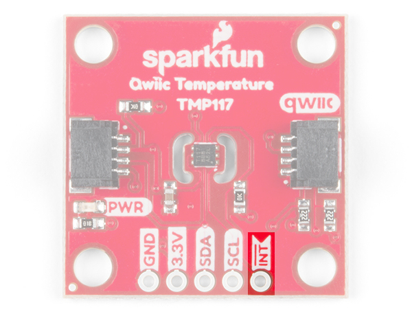
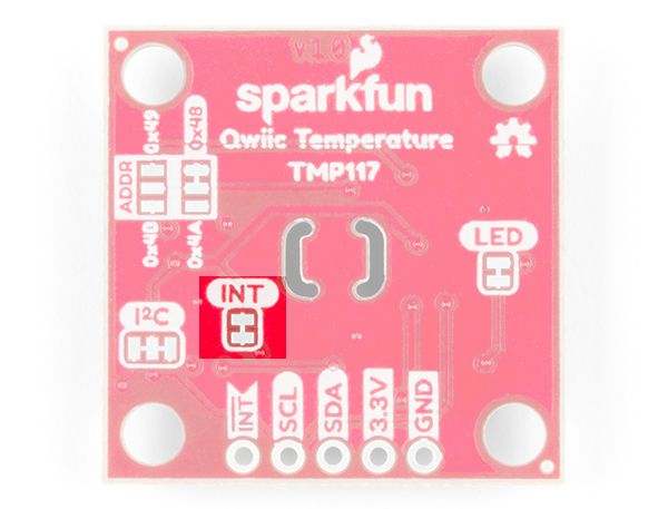
Interrupt Pin (a.k.a. Alert Pin)
The INT pin on the board is connected to the TMP117's "alert" pin. When the pin is active, it will be pulled LOW by default. If the TMP117's temperature limits are configured and the sensor exceeds the values, the alert pin will pulled LOW.
Jumpers
The board has a few jumper pads on the board. If you have not worked with jumper pads, make sure to check out the tutorial on "How to Work with Jumper Pads and PCB Traces" for more information.
How to Work with Jumper Pads and PCB Traces
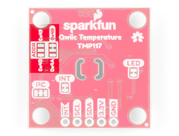
Address Select
The default address of the board is 0x48. If you need to adjust the address of the sensor, you can cut the trace connecting to the default address and add a solder jumper to the respective pads to change the address to 0x49, 0x4A, or 0x4B.
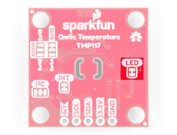
LED
If you need to disable the PWR LED to make the board inconspicuous, conserve more power, or ensure that you are minimizing any heat generated from the LED, you can cut the jumper connecting to the LED.
Pull-Up Resistors
The board also includes jumpers to disable the pull-up resistors on the I2C bus line. If you are using a few I2C devices on the same bus that already have pull-up resistors on their respective boards, you may want to cut the jumpers to disconnect. This is for special use cases when daisy chaining about 7x I2C devices on the same bus. Keep in mind that you will want to avoid heavy bypass traffic on the I2C bus if you are trying to take accurate readings.
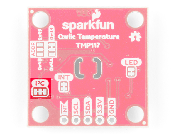
There is also a pull-up resistor on the INT pin if you need to disable it.
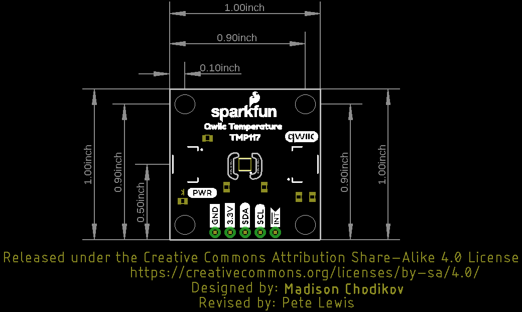
Dimensions
The board uses the standard Qwiic 1.0"x1.0" board size with four mounting holes.