$5.75
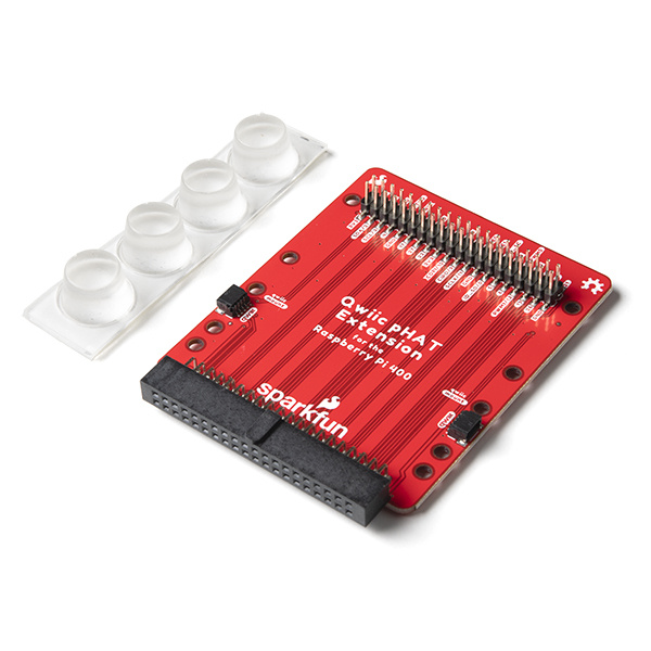
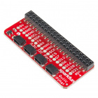
The SparkFun Qwiic pHAT extension for the Raspberry Pi 400 is the quick and easy solution to access the GPIO, stack your favorite pHAT right-side up, or connect a Qwiic-enabled device to the I2C bus (GND, 3.3V, SDA, and SCL).
To follow along with this tutorial, you will need the following materials. You may not need everything though depending on what you have. Add it to your cart, read through the guide, and adjust the cart as necessary.
You'll need a Raspbery Pi 400s. There are two options available. One that is just the Raspberry Pi 400 sold individually. Another that is sold in a kit with everything but the monitor.
Now you probably didn't buy the Qwiic pHAT extension if you didn't have any Qwiic products to use with it, right? If you don't have any Qwiic products, the following might not be a bad place to start since they have a Python drivers written for the devices.
You'll need our handy Qwiic cables to easily connect sensors to your Qwiic pHAT. Below are a few options.


As a desktop, these devices are required. If you received the Raspberry Pi 400 Kit, you'll just need a display and cable. Depending on your display, you may need an HDMI converter to connect to older monitors and TVs.
If you aren't familiar with the Qwiic system, we recommend reading here for an overview.
| Qwiic Connect System |
We would also recommend taking a look at the following tutorials if you aren't familiar with them.
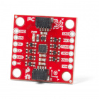
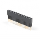
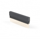
The Qwiic pHAT extension connects to the Raspberry Pi 400's 2x20 port via the right angle header.
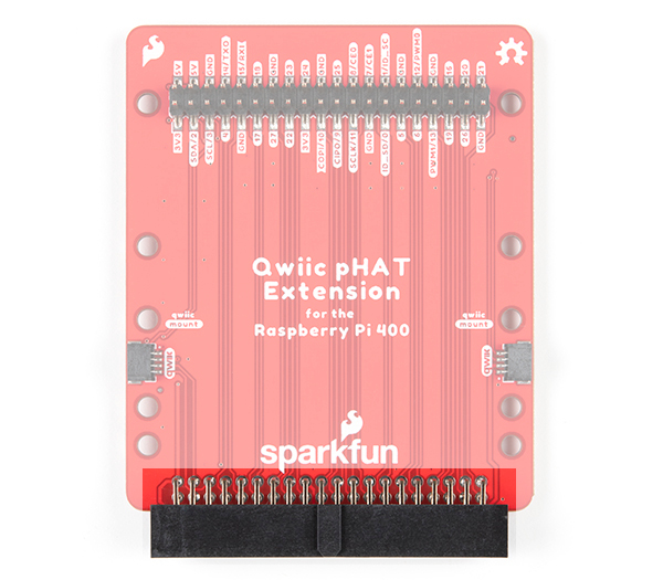
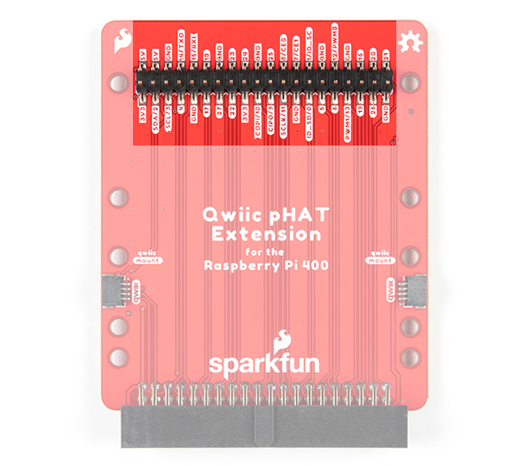
The Raspberry Pi 400's horizontal headers are rerouted and extends out to the vertical headers at the top of the board. Each pin includes a label with their associated pin function.
The Qwiic pHAT extension includes Qwiic connectors on both sides of the board.

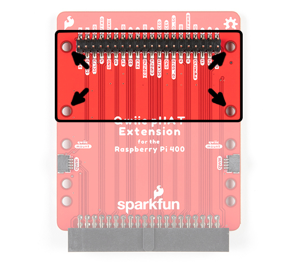
There are 10 mounting holes on the board. Below is the board highlighted for boards designed with the Pi Zero footprint. You can add standoffs to the mounting holes where the arrows are pointing.
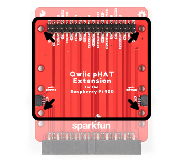
For boards designed with the Raspberry Pi footprint, you can add standoffs to the mounting holes where the arrows are pointing.
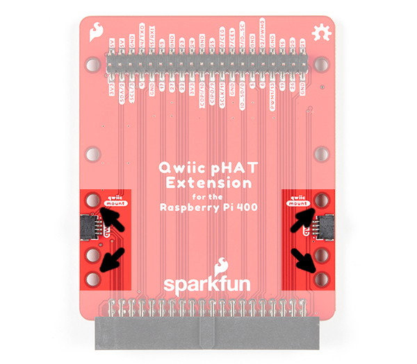
For Qwiic-enabled devices utilizing the standard 1.0"x1.0" sized boards, you can add two standoffs for each Qwiic-enabled device where the arrows are pointing.
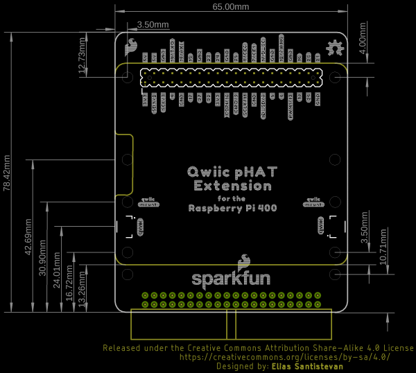
The board is about 65mm x 78.42mm (~2.55in x ~3.08in).

By adding two large silicone bumpers under the board for stability, the height comes to about ~21.32mm (~0.84in) between the header pin and the bottom of the Silicon bumper.
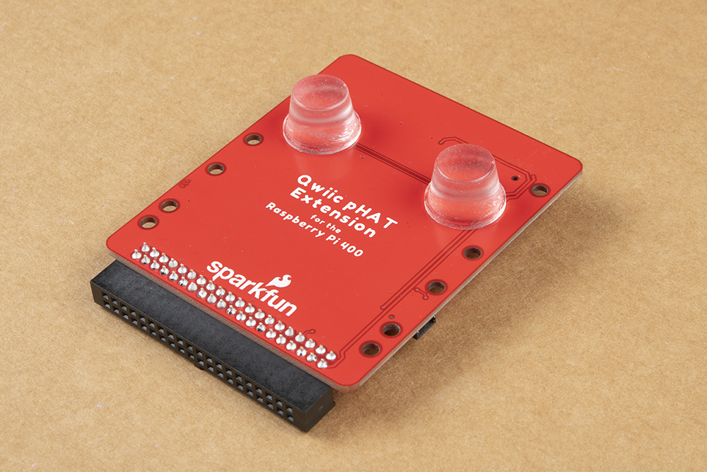
Included with the Qwiic pHAT extension board is a set of large silicone bumpers. These are meant to hold the board up when it is attached to a Raspberry Pi 400 and placed on a table. You only need 2 out of the 4 silicone bumpers so you can use the left over bumpers for other projects.

To attach the two silicone bumpers, peel one bumper and attach it to the bottom of the board between the mounting holes of the Pi Zero's footprint. Repeat for the second bumper. Your setup should look similar to the image below.
At this point, we'll assume that you have flashed an image and inserted the microSD card into the Raspberry Pi 400. With the straight header pins facing up, slide the Qwiic pHAT extension into the Raspberry Pi 400's GPIO port. The right angle connector is keyed so there's only one way to insert the board into the GPIO port.
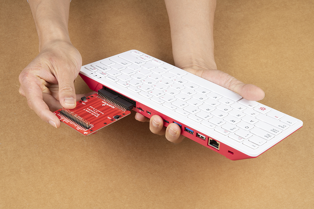
When removing the pHAT extension, simply wiggle the board slowly up and down as the board is being pulled away from the Raspberry Pi 400.
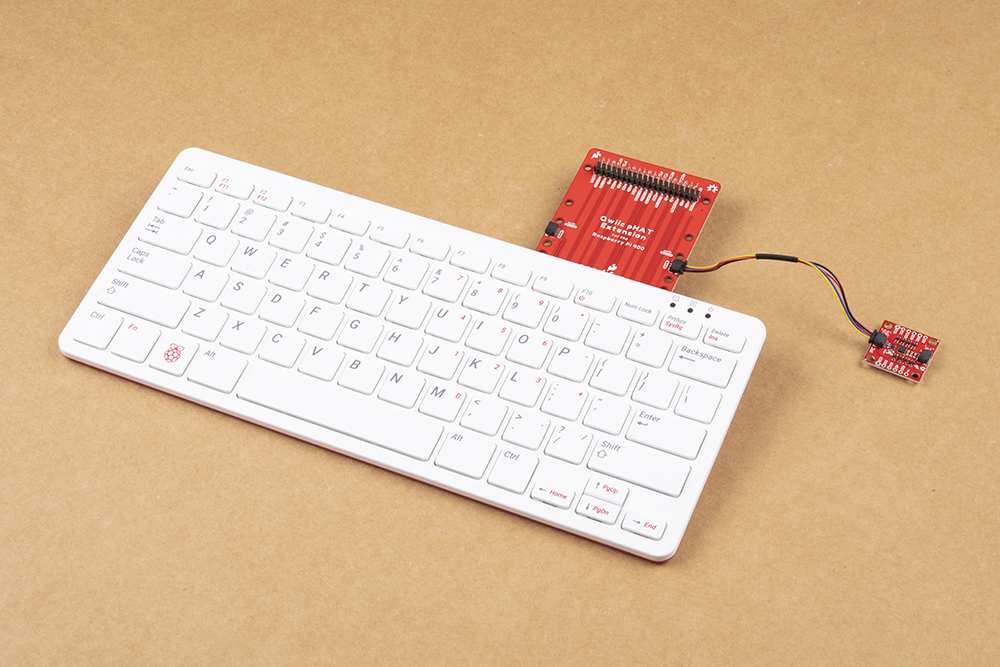
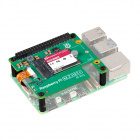
If you have a Qwiic-enabled device, simply insert a Qwiic cable of your choice between the Qwiic board and the Qwiic pHAT extension. While you can connect to either Qwiic connector, the right side of the Qwiic pHAT extension will provide more space since most of the Pi's peripherals will be inserted to the left of the board.
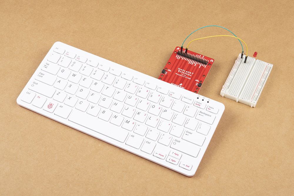
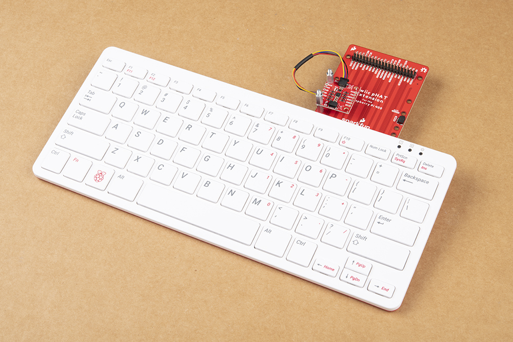
Connecting to the Raspberry Pi 400's GPIO is easy with the pin functions printed on the board for reference. We recommend using M/F jumper wires to connect when prototyping your circuit on a breadboard.
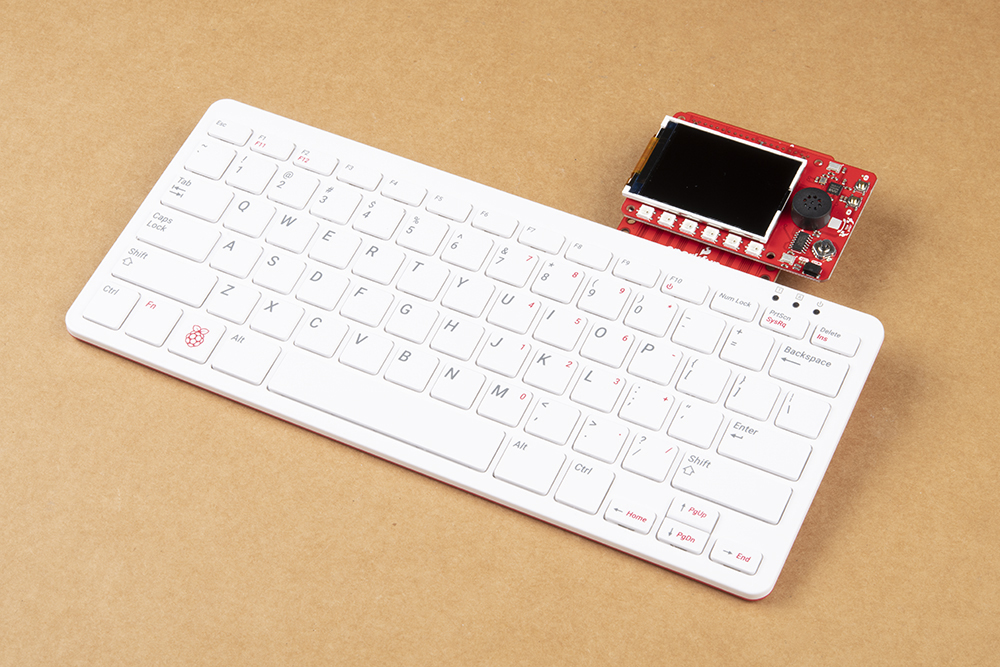
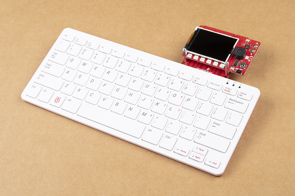
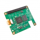
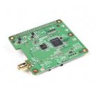
Boards designed with the Raspberry Pi or Pi Zero footprint can be stacked on top of the Qwiic pHAT Extension allowing it to be viewed right-side up. Below is an image of the Top pHAT connected to the Raspberry Pi 400.
Depending on the design of the pHAT, you may require additional height if there are any wires being attached to the bottom of the pHAT. If this is the case, you can add additional height using an extended GPIO headers.
You can attach standoffs to two of the Qwiic mounting holes to secure an Qwiic-enabled device.
Got a wobbly pHAT on the Qwiic pHAT extension? You can attach standoffs to two of the mounting holes across from the vertical header pins on the Qwiic pHAT extension. Of course, you can always use all four mounting holes depending on your personal preference. Below is a Top pHAT using the Raspberry Pi's footprint but you can also mount a board that uses a Raspberry Pi Zero's footprint as well.
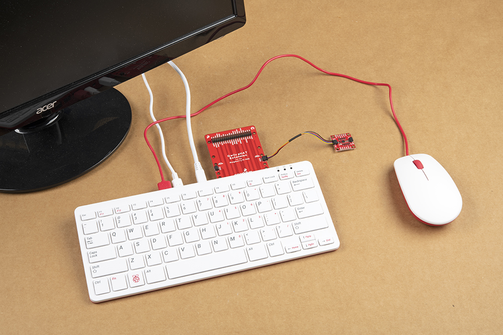
If you have not already, connect your peripherals (e.g. display cable, mouse, power, etc) to the Raspberry Pi 400! Your setup will look similar to the image below.
We recommend checking out the Raspberry Pi 4 Hookup Guide to install the operating system to flash the image to your microSD card for detailed instructions.
If you're starting from scratch with a blank microSD card, you'll want to install Raspbian. If you've already got a working Raspbian system, skip ahead to the next section. Be patient — each of these steps can take a while depending on the speed of your microSD card.
The peripherals are not turned on by default. For those using Qwiic-enabled devices, you will want to enable I2C port. There are two methods to adjust the settings. This is outlined in our Raspberry Pi I2C tutorial.
We've included the following instructions from the tutorial. To enable it, follow the steps below.
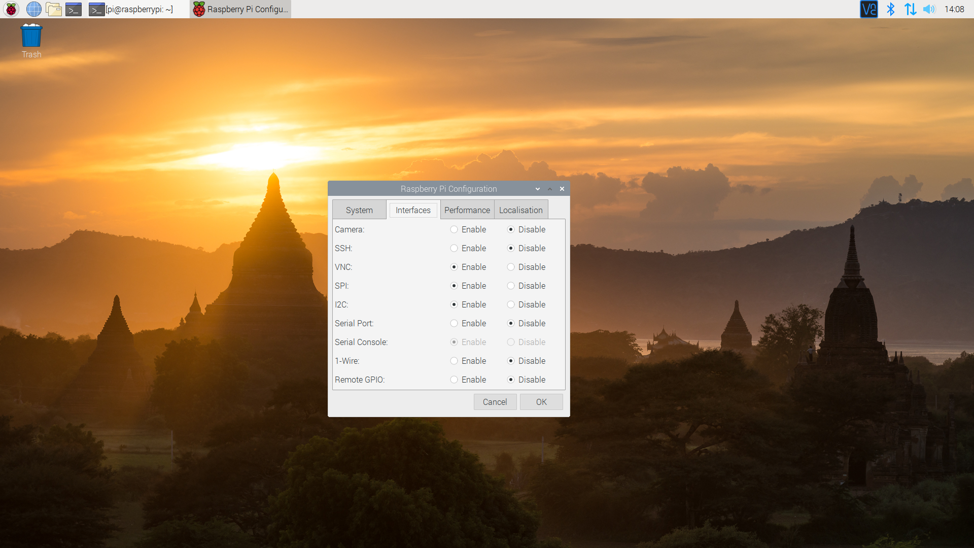
You can use the Desktop GUI by heading to the Pi Start Menu > Preferences > Raspberry Pi Configuration.
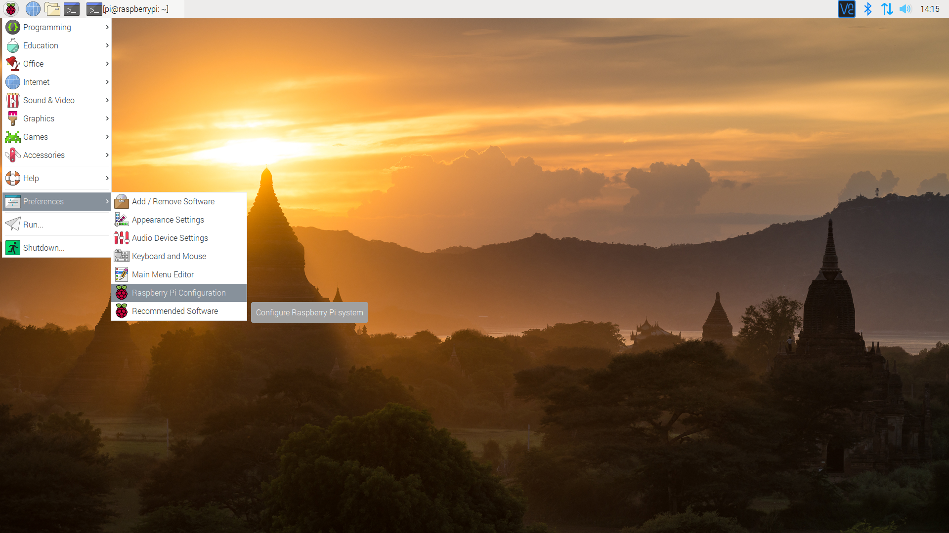
A window will pop up with different tabs to adjust settings. What we are interested is the Interfaces tab. Click on the tab and select Enable for I2C. At this point, you can enable additional interfaces depending on your project needs. Click on the OK button to same.
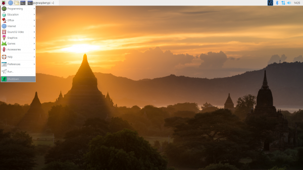
We recommend restarting your Pi to ensure that the changes to take effect. Click on the Pi Start Menu > Preferences > Shutdown. Since we just need to restart, click on the Restart button.
 |
 |
| Shutdown | Turn Off, Restart, Log Off |
Again, we can use raspi-config to enable it.
sudo raspi-config.5 Interfacing OptionsP5 I2C.yes when it asks you to enable I2Cyes if it asks about automatically loading the kernel module.<Finish> button.yes when it asks to reboot.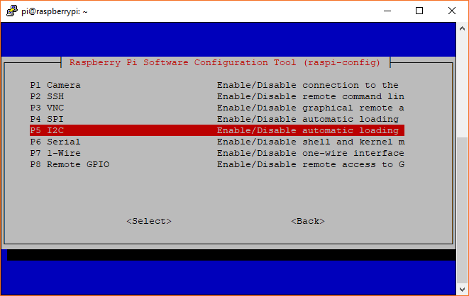
The system will reboot. When it comes back up, log in and enter the following command
language:bash
ls /dev/*i2c*
The Pi should respond with
language:bash
/dev/i2c-1
Which represents the user-mode I2C interface.
If you are using the Raspberry Pi to quickly connect to I2C devices, the best place to start would be to scan for an I2C device on the bus.
There is a set of command-line utility programs that can help get an I2C interface working. You can get them with the apt package manager. Enter the following command.
language:bash
sudo apt-get install -y i2c-tools
In particular, the i2cdetect program will probe all the addresses on a bus, and report whether any devices are present. Enter the following command in the command line. The -y flag will disable interactive mode so that you do not have to wait for confirmation. The 1 indicates that we are scanning for I2C devices on I2C bus 1 (e.g. i2c-1).
language:bash
i2cdetect -y 1
You will get an output from your Raspberry Pi similar to the output below.
language:bash
pi@raspberrypi:~/$ i2cdetect -y 1
     0  1  2  3  4  5  6  7  8  9  a  b  c  d  e  f
00:          -- -- -- -- -- -- -- -- -- -- -- -- --
10: -- -- -- -- -- -- -- -- -- -- -- -- -- -- -- --
20: -- -- -- -- -- -- -- -- -- -- -- -- -- -- -- --
30: -- -- -- -- -- -- -- -- -- -- -- -- -- -- -- --
40: -- -- -- -- -- -- -- -- -- -- -- -- -- -- -- --
50: -- -- -- -- -- -- -- -- -- -- -- -- -- -- -- --
60: 60 -- -- -- -- -- -- -- -- -- -- -- -- -- -- --
70: -- -- -- -- -- -- -- --
This map indicates that there is a peripheral at address 0x60. Your address may vary depending on what is connected to the I2C bus. For advanced users, you can try to read and write its registers using the i2cget, i2cset and i2cdump commands.
Now that you have I2C set up on your Pi, you can start programming your Qwiic devices on your Pi or if you'd like to start with some examples, we have a host of Python drivers for Qwiic breakouts available in the GitHub repository linked below. You can read more about Python for the SparkFun Qwiic system in this blog post.
The Raspberry Pi 400 uses the standard 2x20 GPIO pins. With the help of the Qwiic pHAT extension, the Pi 400's horizontal GPIO pins are rerouted to a vertical position. There are several programming languages available to use on the Raspberry Pi. We recommend Python to control the pins. Check the following tutorials below to get started.
With the Pi 400 2x20 pins rerouted to a vertical position, you can stack on a HAT. Check out a few of the HATs below from the SparkFun catalog.
For more information, check out the resources below:
Now that you have your Qwiic pHAT extension ready to go, it's time incorporate it into a project! Check out any tutorials that are tagged with Raspberry Pi for ideas.
learn.sparkfun.com | CC BY-SA 3.0 | SparkFun Electronics | Niwot, Colorado
