Qwiic MP3 Trigger Hookup Guide
 Nate
Nate 
Hardware Overview
Electrical Characteristics
The Qwiic MP3 Trigger is designed to operate at 3.3V and must not be powered above 3.6V as this is the maximum operating voltage of microSD cards. The 5V power from the USB C connector tied to a robust AP2112 3.3V voltage regulator that can source up to 600mA for the board. Otherwise, the board can also be powered through the Qwiic connector.
Maximum Operating Voltages
All I/O pins are 5V tolerant but the board must but powered at 3.3V.
Recommended Operating Voltages
All I/O pins are designed to function at 3.3V. The board consumes 35mA at 3.3V in standby and can consume over 400mA when driving at 8 Ohm speaker at max volume.
MP3 and ATtiny84
At the heart of the Qwiic MP3 Trigger is the WT2003S MP3 decoder IC. This IC reads MP3s from the microSD card and will automatically mount the SD card as a jump drive if USB is detected. The ATtiny84A receives I2C commands and controls the MP3 decoder.
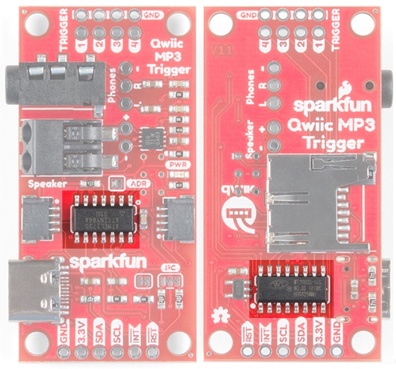
SD and USB
The SparkFun Qwiic MP3 Trigger works with 512MB to 32GB cards formatted in FAT32. We recommend the SparkFun 1GB MicroSD Card because it’s a good mix of low-cost and good performance for MP3 playing. Up to 255 songs can be loaded onto Qwiic MP3 Trigger.
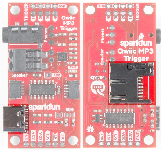
The easiest way to add and remove MP3s to the Qwiic MP3 Trigger is to attach a USB C cable. This will enumerate the microSD card as a jump drive making it extremely easy to access the files on the card. Alternatively, if you don’t want to use USB, you can eject the microSD card and read/write to it using a normal USB SD adapter.
Qwiic Connectors
The Qwiic MP3 Trigger from SparkFun includes two Qwiic connectors to make daisy chaining this music player with a large variety of I2C devices. Checkout Qwiic for your next project.
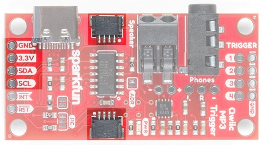
The I2C pins broken out on the board are tied directly to the Qwiic connectors.
Audio Amplifier
The speaker is boosted by a Class-D mono amplifier capable of outputting up to 1.4W. What does 1.4W mean? It's incredibly loud; great for making sure your mech effects are heard on the *con floor (i.e. _Comic_ - con, _Def_ - con, etc.) and wonderful for annoying your officemates. Both outputs have volume controlled by the SET_VOLUME command and is selectable between 32 levels. Additionally, there are PTH holes beside both connectors if a soldered connection is preferred.

0x07 command (see Command Set section). The volume setting is saved to NVM (non-volatile memory) and loaded at power on.
Audio Outputs
A standard 3.5mm audio jack is provided making it easy to play your tunes over headphones or amplified desktop speakers like our Hamburger Speaker or any other amplifier.
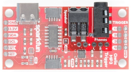
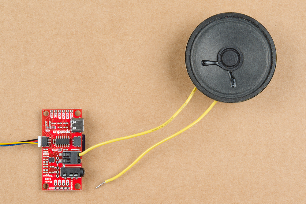
A poke-home connector labeled Speaker is also provided in parallel to the 3.5mm jack. This is a friction fit type connector; simply push stranded or solid core wire (22AWG or larger) into the hole and the connector will grip the wire.
To use an external speaker, solder two wires onto the speaker and insert the wires into the poke home connector.
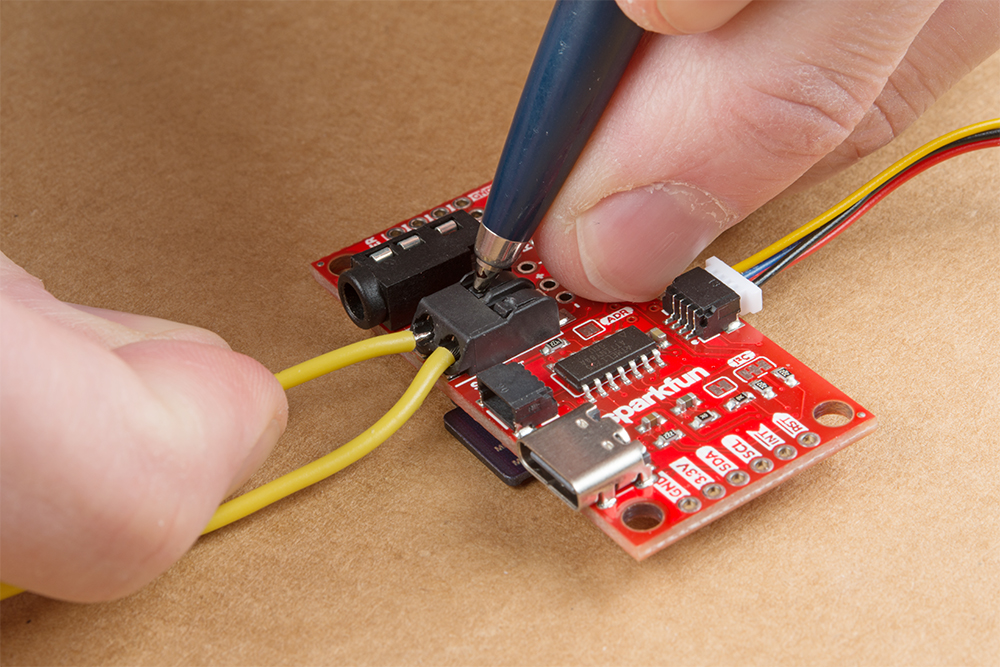
To remove, push down on the tab with a ballpoint pen and gently pull on the wire.
Jumpers
The Qwiic MP3 Trigger has three jumpers shown below:
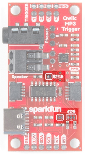
The default 7-bit I2C address of the Qwiic MP3 Trigger is 0x37. The ADR jumper is open be default and can be closed with solder to force the device’s I2C address to 0x36. This is handy if you need to have two Triggers on the same bus. If you need more than two devices on the bus, or if these addresses conflict with another I2C device the address can be changed in software. Please see the Command Set.
Cutting the I2C jumper will remove the 2.2k Ohm resistors from the I2C bus. If you have many devices on your I2C bus you may want to remove these jumpers. Not sure how to cut a jumper? Read here!
The INT jumper is located below the SparkFun logo and connects a 10K pull-up resistor to the INT pin. If you have multiple, open-drain, interrupt pins connected together you may want to remove this pull-up to better control the pull-up resistance.
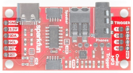
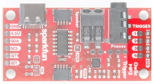
I/O Pins
There are several I/O pins broken out on the board, which are described in the table below.
| Pin Name | Type | Description |
|---|---|---|
| RST | Input | Active low. Pull this pin low to reset the ATtiny84A, effectively resetting the Qwiic MP3 Trigger. |
| INT | Output | Active low. Goes low when track is finished playing. Goes high again when CLEAR_INTERRUPTS command is issued. |
| SCL | Input | Serial clock line of I2C interface. Qwiic MP3 Trigger does implement clock stretching and will hold the clock line low if it is unable to receive additional I2C data. |
| SDA | Input/Output | Serial data line of I2C interface. |
| 3.3V | Power | Qwiic MP3 Trigger can be powered from 2.8V to 3.3V. Anything greater than 3.6V will damage the microSD card. |
| GND | Power | The ground pin. |
| Trigger 1-4 | Input | When a trigger pin is pulled to ground, the corresponding T00X.mp3 file is played. Pins can be combined to play T001 to T010. Pins are 5V tolerant. |
Triggers
There are four trigger pins at the top of the board. When pulled low these pins begin playing whatever file is named T001.mp3 to T010.mp3. For example, if you attach a momentary button to Pin 3 and GND, when you press that button the T003.mp3 file will immediately be played. This allows you to start playing sound effects with the touch of a button without any programming!
Single Trigger
For a basic triggered setup, load four files named T001.mp3, T002.mp3, T003.mp3, and T004.mp3 on the microSD card. Use a wire or button to connect a trigger pin to ground and the associated track will begin playing. Once you have the setup working, use any momentary button to allow a user to cause an MP3 to start playing.
Using Multiple Triggers
By pulling multiple pins down simultaneously the four triggers can play up to ten tracks: T001 to T010. When a trigger pin is detected the pin values are added together. For example, pulling pins 2 and 4 low at the same time will play track T006.mp3 as will pulling pins 1, 2, and 3 low at the same time.
- The trigger pins are constantly monitored and any change in pins will immediately cause the new track to begin playing.
- Indefinitely holding a pin low will cause the same track to play again. This allows for looping sound effects.
Interrupt Pin
The Qwiic MP3 Trigger has an INT pin which is configured as an open-drain pin with an on board 10K Ohm pull-up.
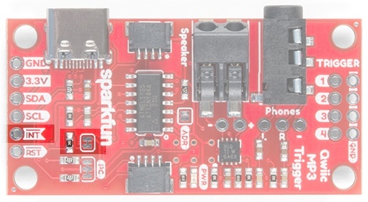
The INT pin will go low when a track has stopped playing. Once the CLEAR_INTERRUPTS 0x0D command has been received, the INT pin will become high-impedance and will return to a high level.
If you have multiple devices with bussed interrupt pins you may want to cut the INT jumper to remove the 10K pull-up resistor.