Qwiic Micro Magnetometer - MMC5983MA Hookup Guide
Hardware Overview
The beautiful thing about this Qwiic board is that it is extremely simple. Let's dive in and have a look at its features!
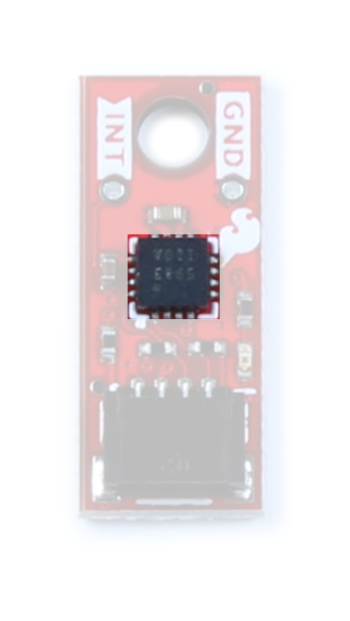
MMC5983MA
The MMC5983MA is an AEC-Q100 qualified, fully integrated 3-axis magnetic sensor with on-chip signal processing and integrated I2C/SPI bus. It has superior dynamic range and accuracy with ±8G FSR, 18bit operation, 0.4mG total RMS noise, and can enable heading accuracy of 0.5º. More information can be found in the datasheet.
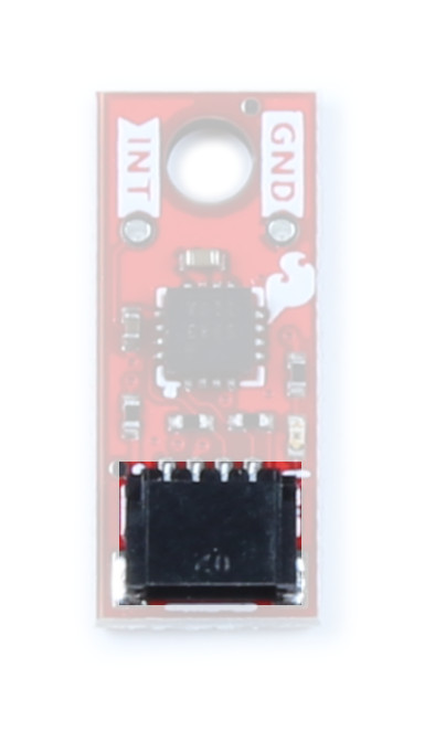
Qwiic Connector
Our Qwiic Ecosystem makes sensors pretty much plug and play. There's a Qwiic connector on the side of the Qwiic Micro Magnetometer to provide power and I2C connectivity simultaneously. The default I2C address is 0x30.
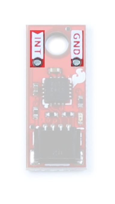
Pins
We've broken out the interrupt and ground pins to PTH on either side of the board. The interrupt pin is active high - writing “1” will enable the interrupt for completed measurements. Once a measurement is finished, either magnetic field or temperature, an interrupt will be sent to the host.
Jumpers
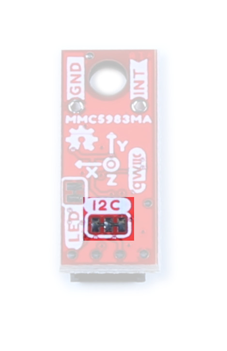
I2C
Like our other Qwiic boards, the Qwiic Micro Magnetometer comes equipped with pull-up resistors on the clock and data pins. If you are daisy-chaining multiple Qwiic devices, you will want to cut this jumper; if multiple sensors are connected to the bus with the pull-up resistors enabled, the parallel equivalent resistance will create too strong of a pull-up for the bus to operate correctly. As a general rule of thumb, disable all but one pair of pull-up resistors if multiple devices are connected to the bus. To disable the pull up resistors, use an X-acto knife to cut the joint between the two jumper pads highlighted here.
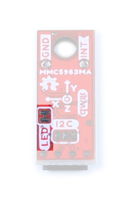
LED
If power consumption is an issue, cutting this jumper will disable the Power LED on the front of the board.
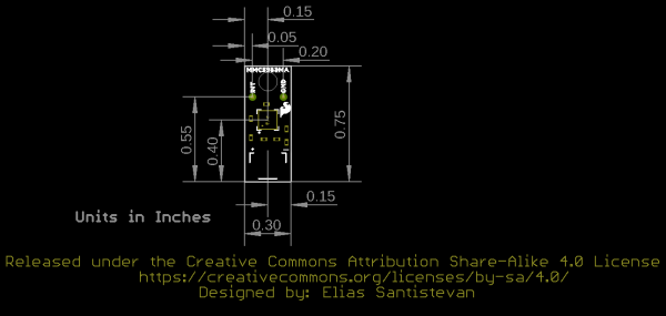
Board Outline
This ultra tiny Qwiic breakout board measures 0.75" x 0.30".
